© 2001 – Ericsson Amplifier Technologies Inc.
15
3.2.3 Remote Control/Status Interface
The MCPA is equipped with control inputs and status outputs at the I/O interface.
Section 2.7 details the interfaces for the Blind mate configurations and describes the
signals.
3.3 Initial Turn On Procedure
The following procedure is intended to verify operation of the MCPA following
installation, repair or replacement.
WARNING
EQUIPMENT OPERATORS MUST BE FAMILIAR WITH
ALL SAFETY PRECAUTIONS OUTLINED AT THE
BEGINNING OF THIS SECTION PRIOR TO OPERATING
THE MCPA. OPERATOR INJURY AND/OR EQUIPMENT
DAMAGE WILL RESULT FROM IMPROPER OPERATION.
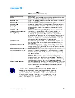
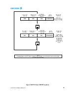
a. Verify that all connections to the MCPA have been properly made in accordance with
Section 2 of this manual, and the outline and installation drawing, Figure 2.
NOTE
When +27VDC is initially connected and applied to the
amplifier, all of the LED’s on the front panel, except for the
DC ON, will illuminate momentarily. This is a normal
condition.
b. With no RF applied to the MCPA, press the POWER ON/OFF switch once. The DC
ON LED (part of the ON/OFF switch) will be illuminated, and the fans will be activated.
c. Observe that
only
the following indicators are illuminated on the MCPA front panel:
DC ON
ENABLE
d. Apply reduced RF input (-40 dBm) to the MCPA RF IN connector within the 869-894
MHz frequency range, and observe that
only
the DC ON and ENABLE LED indicators
remain illuminated.


