© 2001 – Ericsson Amplifier Technologies Inc.
20
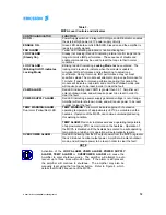
of the RF signals. The microprocessor controls the amplitude and phase adjustments
of the two loops. The loop processor responds to the amplitude and phase of the IMD
loops. In the event of a failure of the loops or processor, the front panel LOOP alarm
indicator will be illuminated, and further operation of the MCPA will be inhibited. The
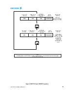
fault condition may be reset by re-setting power to the MCPA. Refer to Figure 4 for
sequence.
4.4.4 Amplifier Module Cooling
The amplifier is cooled via forced air through the heatsink. Two rear fans are used to
draw air through the heatsink. The fans are field replaceable and are monitored for fan
faults. In the event of a fan failure, the front panel FAN alarm indicator will be
illuminated. Operation of the MCPA will continue, however, at some point, the TEMP
WARN/ALARM circuitry may be activated due to reduced cooling, and may inhibit
MCPA operation (refer to paragraph 4.4.1). The fan(s) are externally mounted and are
easily replaced without removal of any of the MCPA covers, and without the need to
shut down the MCPA. Refer to Maintenance section 5.4 for fan assembly replacement
and ordering instructions.
4.5 Power Distribution
The amplifier employs a DC/DC converter to regulate the amplifier sub-circuits to the
required voltage, based on a 26-28 VDC input. The power supply board converts the
input voltage to +/-5V, and +/-15V used by the loop processor and microprocessor.
Internal monitoring circuitry monitors the supply voltages, and activates the front panel
POWER SUPPLY alarm LED indicator in the event of a fault. Operation of the MCPA
is inhibited following detection of this fault . The fault condition may be reset by re-
setting power to the MCPA. Refer to Figure 4 for sequence.
4.6 Intermodulation Distortion Performance
The MCPA amplifier is designed to deliver a 120W average power, multicarrier signal,
with extremely low intermodulation products, over the passband of 869-894 MHz.
4.6.1 Intermodulation Distortion
When measured with fifty (50) random phase sets, intermodulation products are
below -63 dBc.
4.7 Description of Operating Modes
4.7.1
Default
mode
When
initially
powered up (or installed into the shelf), the MCPA amplifier defaults to
the standby mode after a brief initialization sequence is completed. During the
initialization sequence, the LEDs on the front panel will briefly illuminate.


