


1/2" AIR RATCHET WRENCH
WARNING! Compressed air can be dangerous. Ensure that you
are familiar with all precautions relating to the use of compres-
sors and compressed air supply.
1. Use only clean, dry, regulated compressed air as the power source.
2. Air compressors used with the tool must comply with the appropriate European
Community Safety Directives.
3. Make sure that the air compressor being used for the tool operation supplies the
correct output (CFM).
4. Have the tool in "off" position when connecting the tool to the air supply.
5. Use normal 90psi working pressure for the tool. High pressure and unclean air will
shorten the tool life due to the faster wear and also may create a safety hazard.
6. Drain water from the air compressor tank daily, as well as any condensation in the
air lines. Water in the air line may enter the tool and cause damage to the tool
mechanisms at operation.
7. Clean the tool air inlet screen filter for blockage weekly. Clean if necessary.
8. Usually a 3/8" (inner diameter) air hose is recommended for air supply and airflow
to get the optimum performance of tool.
9. A long air hose (usually over 8 meters) may cause up to 15psi drop in pressure, so
you need to set the output pressure of the air compressor higher to maintain the
required working pressure at the tool.
10. Use proper hoses and fittings. We do not suggest connecting quick change
couplings directly to the tool since they may cause failure due to tool vibration at
operation. Instead, add a lead hose and connect coupling between air supply and
hose whip.
11. Check hoses for wear before each use. Make certain that all connections are in
security.
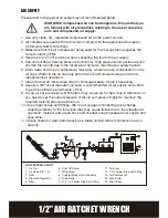
AIR SUPPLY
6. Shut Off Valve
7. Whip Hose
8. Coupler Body And Connector
9. Drain Daily
10. 1/2" Or Larger Pipe And Fitting
AIR SYSTEM LAYOUT
:
1. Air Tool
2. Air Hose 3/8" (I.D.)
3. Oiler
4. Pressure Regulator
5. Filter
11. Air Dryer
12. 1" Or Larger Pipe And Fitting
13. Air Compressor
14. Auto Drain
15. Drain Daily
6
9
13
14
15
8
7
12
10
5
4
3
2
11
1
Please refer to the typical air system layout recommended below.
Summary of Contents for ERN634ATL
Page 1: ...1 2 AIR RATCHET WRENCH ERN634ATL...
Page 16: ...1 2 AIR RATCHET WRENCH...