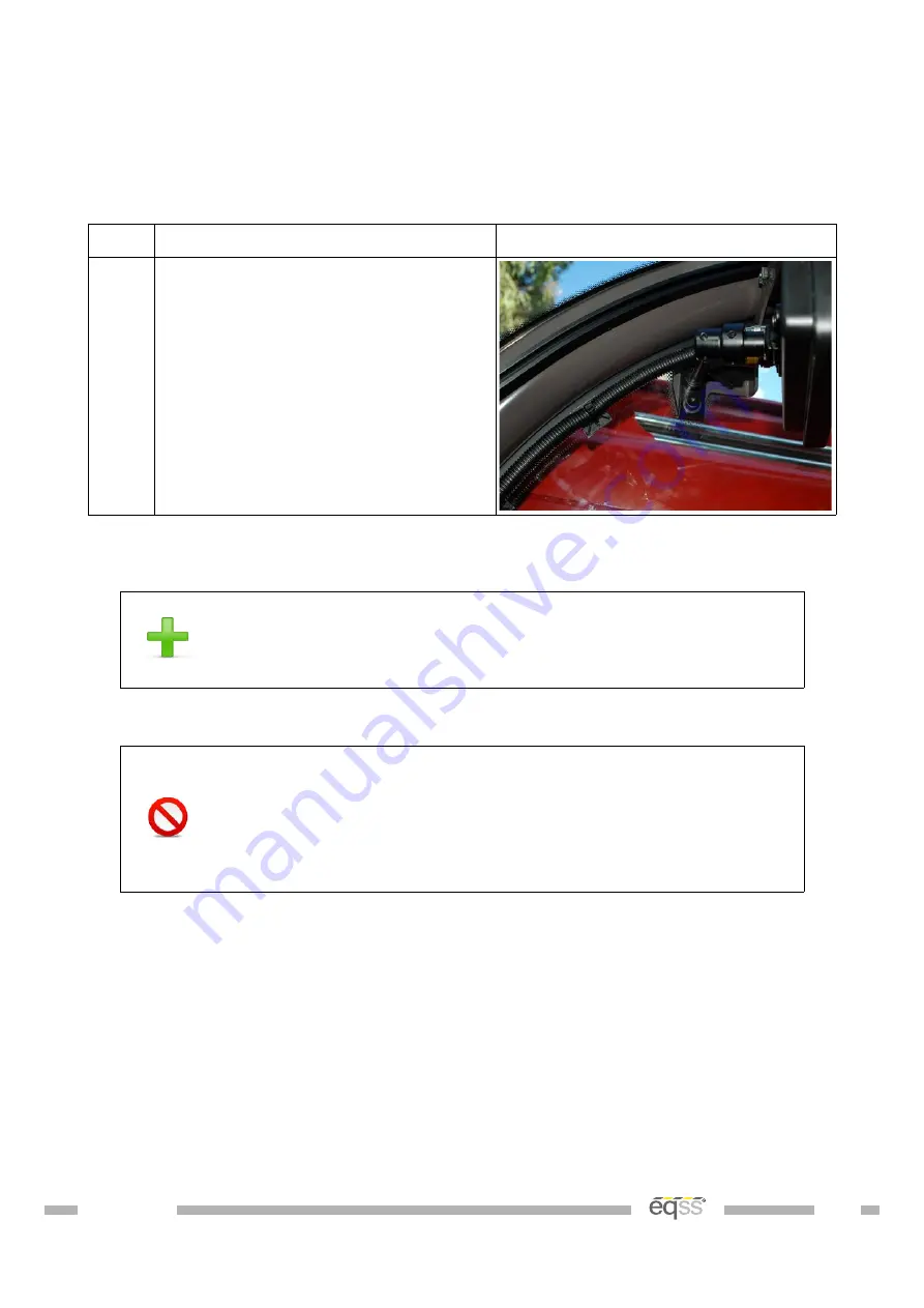
Display Installation
The display shows the current safety status of the telehandler.
Step
Description
Diagram
1.
Attach the display bracket to the
level indicator in the top right corner
using the supplied
M6 x 35 mm bolts and nuts.
Attach the display to the bracket and
tighten the grub screw
Table 13: Display Installation
Adjust the display bracket for optimal viewing angle once the
display is powered
If the M12 screw lock connectors on the display are over
tightened it will twist the connector pins attaching the
connector to the PCB. See Appendix A: Attaching Display
Connectors on page 47 for the correct method of attaching to
the display connectors.
32 of 53
Summary of Contents for Gen-3 LMS
Page 5: ...Appendix B Reattach Ferrites 51 Indexes and Tables 52 VER 1805241756 5 of 53...
Page 9: ...Illustration 1 Machine Boom VER 1805241756 9 of 53...
Page 10: ...Illustration 2 Machine Chassis VER 1805241756 10 of 53...
Page 43: ...Complete the system checklist once installation has been completed VER 1805241756 43 of 53...


