EPSON Stylus
&2/25
800
Rev. A
3-52
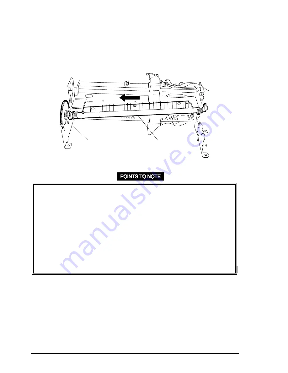
4. Push levers out to release the lock levers for the right and left bushings (12 mm) securing
the paper feed roller assembly to the right and left frames. Then turn them forward until they
fit through the cutouts in the frames. Shift the paper feed roller assembly left, and remove
the paper feed roller assembly and rear paper guide along with the gear (70 mm) by lifting
upward. (See Figure 3-68.)
❏
When installing the paper feed roller assembly into the right and left frames, insert the
right and left bushing on the left of each frame. Then align the bushings with the cutouts
in the frame, and slide the shaft to the right.
❏
Make sure that the bumps on each bushing lever fit into the location holes in the frames.
(See Figure 3-69.)
❏
If you dismount the gear (70 mm) after removing the paper feed roller assembly, be sure
to press the gear back into the paper feed roller assembly before reinstalling the paper
feed roller assembly to the right and left frames. Do not hold the gear by its teeth during
this operation.
❏
Make sure that 3 hooks fixing the rear paper guide to the bottom frame securely fit into
the cutouts in the bottom frame.
❏
Make sure the contact spring on the left is correctly mounted onto the bottom frame, as
shown in Figure 3-70.
Gear (70)
Paper Feed Roller Assembly
Figure 3-67. Paper Feed Roller Assembly Removal


