EPSON Stylus COLOR 860/1160
Revision C
Operating Principles
Electrical Circuit Operating Principles
41
2.2.1 C298PSB/PSE Board
The Stylus COLOR 860 and Stylus COLOR 1160 are equipped with the
C298PSB/PSE, the common power supply board for the both products. The
basic structure of the circuit is the same as for the C257PSB/PSE board used
in the Stylus COLOR 740. The power supply boards of these printers use a
RCC switching regulator, which gen42VDC for drive line and +5VDC
for logic line to drive the printer. For one of the major characteristics of the
C298PSB/PSE, it uses the secondary switch that is also used in the Stylus
Color series. Use of the secondary switch enable the circuit to keep supplying
voltage to 5 V line and 24 V line for approximately 30 seconds if the printer
power is turned off through the panel switch. This extra time allows the printer
to perform the following operations when the printer is turned off through the
panel switch while it is in operation.
o
When the printer is in a printing state, if the CR unit is away from the home
position, the CR unit can return to the home position to be locked before
the printer power shuts down.
o
When the printer is not in a printing state, if paper fed from ASF remains in
the printer, the paper is ejected before the printer power shuts down.
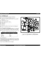
Table 2-9 in the right column shows the application of each voltage generated
by C298PSB/PSE board.
NOTE:
The 5VDC is only applied to the parts and locations shown in the Table 2-9.
The C298MAIN, like the C267MAIN-B board*, uses the 3.3V drive chips for
most of the logic line chips (CPU, ASIC, ROM, DRAM). For this reason, those
chips are not driven by the +5VDC but 3.3VDC that is reduced by the IC9
(3.3VDC regulator) on the C298Main Board.
* Used in the minor changed models of the Stylus COLOR 740, Stylus Pro
750, and Stylus Pro 1200.
Figure 2-15 in the right column shows the block diagram for the C298PSB/PSE
board. The process from the input of AC voltage to the output of 42 V DC and 5
V is explained in the following page.
Table 2-9. Application of the DC Voltages
Figure 2-15. C298PSB/PSE Board Block Diagram
Voltage
Application
+42VDC
CR Motor, ASF/Pump Motor, PF Motor
Head driving power supply
+5VDC
Sensor circuit power supply voltage
LED panel drive power supply
Nozzle selector control signal voltage
I/F Control Circuit
Slave CPU for DC motor control
F 1 , T H 1
C 1 1
L 1 , C 1 , C 2
D B 1
T R A N S ( T 1 )
O v e r C u r r e n t
P r o t e c t i o n
F i l t e r C i r c i u t
F u l l W a v e
R e c t i f i e r c i r c u i t
S m o o t h i n g
C i r c u i t
M a i n S w i t c h i n g
C i r c u i t
Q 1
A b n o r m a l
F e e d b a c k c i r c u i t
Q 2 , Q 3 , Q 3 1
P h o t o
C o u p l e r
P C 1
D 5 1
A C I n p u t
S m o o t h i n g
C i r c u i t
C 5 1
+ 4 2 V D C L i n e
C o n s t a n t C o n t r o l
Z D 8 1 - 8 6 , Z D 5 1
P o w e r D r o p
D e l a y C i r c u i t
C 8 4 , Q 8 4
+ 4 2 V D C L i n e
O v e r V o l t a g e
L i m i t a t i o n
Z D 5 2 , 8 7
+ 5 V R e g u l a t o r
I C 5 1
+ 4 2 V D C
+ 5 V D C
+ 5 V D C L i n e
O v e r V o l t a g e
L i m i t a t i o n
P S C S i g n a l
f r o m M a i n b o a r d
Z D 5 3
+ 4 2 V D C L i n D r o p
L i m i t a t i o n C i r c u i t
Z D 9 0
Summary of Contents for Stylus COLOR 1160
Page 8: ...C H A P T E R PRODUCTDESCRIPTION ...
Page 28: ...C H A P T E R OPERATINGPRINCIPLES ...
Page 53: ...C H A P T E R TROUBLESHOOTING ...
Page 74: ...C H A P T E R DISASSEMBLYANDASSEMBLY ...
Page 116: ...C H A P T E R ADJUSTMENT ...
Page 150: ...C H A P T E R MAINTENANCE ...
Page 160: ...APPENDIX C H A P T E R ...


