TROUBLESHOOTING
Rev. A
5-5
Step
Cause
Check Point
Decision
Solution
1
The power supply unit
is defective.
Detach CN3 on the power supply unit.
Check the CN3 is outputting the
following voltages:
(+): Pin 3 of CN3
(-): Pin 5 of CN3
Is the output v24 VDC?
No
Replace the power
supply board.
2
The engine mechanism
is defective.
•
Remove the upper case. Does the
main scan motor rotate at the power
switch is on ?
•
Remove the main scan motor from
the engine mechanism. Does the
carrier table move smoothly?
No
Check the carrier
movement
mechanism and
decide to do
overhaul or the
entire unit
replacement.
3
The main scan motor is
defective.
Disconnect the CN3 on the digital board
unit then detach the following main
scan motor connector terminal by
multimeter with resistance measuring
range.
Pin 2 and Pin 4
Pin 1 and Pin 3
Is the motor coil resistance value
APPROX. 8 ohms?
No
Replace the main
scan motor.
If the motor coil is opened, check the
main scan motor drive circuit on the
digital board unit as follows:
a) Adjust the multimeter with
resistance measuring range.
b) Turn the scanner power off.
c) Detach the (-) terminal of the
multimeter on CN3 pins 1,2,3, and 4
of the digital board unit.
d) Detach the (+) terminal of the
multimeter on GND of the digital
board unit.
Does the multimeter detect “
∞
”?
No
Replace the main
scan motor and
the digital board
unit.
4
The digital board unit is
defective.
--
--
Replace the digital
board unit.
Step
Cause
Check Point
Decision
Solution
1
Photo interrupter A (for main
scanning ) is defective.
--
--
Replace the photo
interrupter A.
Table 5-7.
The carrier unit does not move
Table 5-8. C
arrier unit moves though Error is displayed
Summary of Contents for FILMSCAN 200
Page 1: ...EPSON FILM SCANNER FilmScan 200 SERVICE MANUAL SEIKO EPSON CORPORATION 4007375 ...
Page 5: ...v REVISION SHEET Revision Issued Data Contents Rev A FEBRUARY 28 1997 First issue ...
Page 8: ...EPSON SEIKO EPSON CORPORATION ...
Page 75: ...CHAPTER 4 ADJUSTMENT No adjustment is required in this product ...
Page 85: ...CHAPTER 6 MAINTENENCE 6 1 MAINTENENCE 6 1 6 2 LUBRICATION 6 1 ...
Page 86: ...APPENDIX A 1 CONNECTOR PIN ASSIGNMENTS 1 A 2 EXPLOED DIAGRAM 8 ...
Page 88: ...FilmScan 200 Rev A A 2 Figure A 2 Cable Connection SCSI Model ...
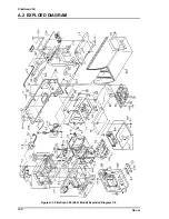
Page 95: ...APPENDIX Rev A A 9 Figure A 4 FilmScan 200 Bi D Model Exploded Diagram 2 2 ...
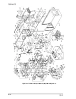
Page 96: ...FilmScan 200 Rev A A 10 Figure A 5 FilmScan 200 SCSI Model Exploded Diagram 1 2 ...
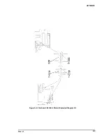
Page 97: ...APPENDIX Rev A A 11 Figure A 6 FilmScan 200 SCSI Model Exploded Diagram 2 2 ...
Page 98: ...FilmScan 200 Rev A A 12 Figure A 7 APS Holder option Exploded Diagram ...
Page 100: ...FilmScan 200 Rev A 6 2 Shaft 1 G 36 1 G 36 Figure 6 1 Lubrication Points ...


