


Disassembly and
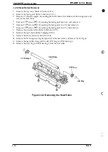
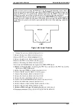
3.2.4.12 Control Panel Removal
1.
2.
3
5.
6.
7.
Remove the top cover. (Refer to Section 3.2.1.2.)
Remove the left cover.
to Section 3.2.1.3.)
Remove the BTR assembly. (Refer to Section 3-2.4.4.)
Remove the trans. chute assembly. (Refer to Section 32.4.7.)
Remove the link assembly. (Refer to Section 3.2.4.1.)
Remove 5 CBB screws
x 8) securing the front frame assembly to the front rover.
connector
from the control panel, and remove the panel while pushing 2
hooks..
3-35. Removing the Control Panel
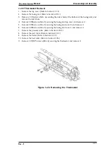
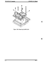
3.2.4.13
Tray Removal
the
tray.
2. Remove the
tray from the left side.
Figure 3-36. Removing the
Tray
3-22
Rev.