


Installation Instructions
AN2 Series
15
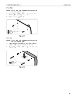
Calibrating Finger Touch Unit (FTU)
1.
Snap calibration marker spacers (QQ) into bottom of
calibration markers included with Epson projector. (See
Figure 23)
NOTE:
Ensure that magnet on calibration marker spacer (QQ)
lines up with target on calibration marker. (See
Figure 23)
Figure 23
2.
Calibrate the finger touch unit (FTU) following instructions
included with the Epson projector.
Attaching Sensor Cover and Outer Cover
1.
Reattach the sensor cover, using the fastener previously
removed. (See Figure 2)
Figure 24
2.
Hold sensor outer cover (U) under boom projector mount
and begin sliding downward toward top of whiteboard. (See
Figure 25)
3.
Continue sliding cover downward until tabs at bottom of
cover slip into slot on top of whiteboard. (See Figure 25)
Figure 25
Attaching Marker Tray
1.
Attach marker tray (FF) at any point along bottom of
whiteboard using two #8 x 1/2" self-drilling screws (CC).
(See Figure 26)
Figure 26
Calibration
marker
Magnet
Target
(QQ) x 2
1
1
1
Tab on bottom
of sensor cover
Top of screen
2
3
(FF)
1
(CC) x 2
Screen


