Adjustment
Rev. A
4-5
4.1.3 Head Voltage Write Operation
This operation is performed to write the print head drive voltages in the EEPROM. You need to perform
this operation whenever you replace the prihthead.
1.
Connect the printer and the host computer with a parallel interface cable.
2.
Run the adjustment program in the host computer.
3.
Input the customer data. (Refer to Section 4.1.2.)
4.
Move the cursor using
or
key to select
“ADJUST”
in the 1st menu. Then press t
he
Enter
Key
, and
the main menu appears on the monitor.
5.
Move the cursor using
or
key to select “
HEAD VOLTAGE WRITE”
. Then press the Enter key, and the
“
HEAD VOLTAGE WRITE”
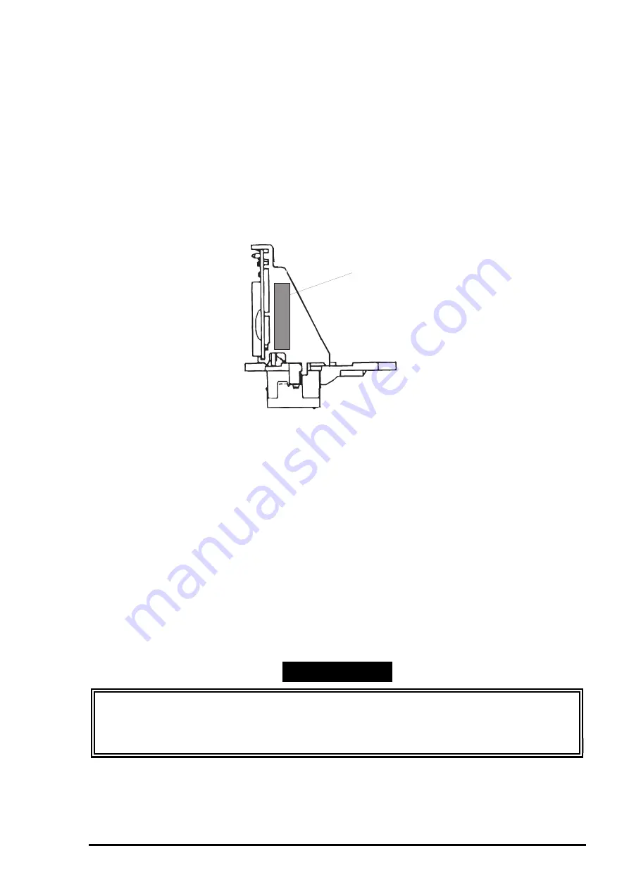
program starts. You are to input the data for the black head. The head ID
(head voltage) is marked on the left side of the head, as shown below.
6.
Write the black head ID (head voltage), which is composed of 5 digits, as shown below,. The first 2
digits and the following 2 digits indicate the head ID for the normal dot and head ID for microweave
dot respectively. The last digit indicates the rank value.
Black Voltage (5- digit-ID) :
* * * * *
Color Voltage (5 digit-ID) :
* * * * *
7.
Press the Space key if you correct a wrong ID. Enter “0” to exit “
HEAD VOLTAGE WRITE”
, and the main
menu appears on the monitor.
Note If the Enter key is pressed, the initial ink charge is performed and the program returns to the
main menu.
8.
Select other adjustment menu using
or
key, or select “
RETURN TO 1st MENU”
to exit the main
menu.
9.
Move the cursor using
or
key to select “
END”
and press
the
Enter
key to exit the adjustment
program.
WORK POINT
Adjusted values are not stored in the EEPROM until the printer is turned off. Therefore be sure to
turn off the printer once after the adjustment program is executed.
The set value is transferred to the printer when this operation is executed. Therefore do not turn
off the printer before exiting “
HEAD VOLTAGE WRITE”
.
Head Voltage Marking
Figure 4-3. Head ID Marking
Summary of Contents for 1520 - Stylus Color Inkjet Printer
Page 138: ...Maintenance Rev A 6 5 8 9 10 10 10 10 10 10 10 10 Figure 6 2 Lubrication Points 2 ...
Page 146: ...Appendix Rev A A 7 A 2 Circuit Diagrams Figure A A 2 C211 MAIN B Board Circuit Diagram 1 2 ...
Page 147: ...EPSON Stylus COLOR 1520 Rev A A 8 ...
Page 148: ...Appendix Rev A A 9 Figure A A 3 C211 MAIN B Board Circuit Diagram 2 2 ...
Page 149: ...EPSON Stylus COLOR 1520 Rev A A 10 ...
Page 152: ...Appendix Rev A A 13 A 3 Component Layout Figure A A 6 C211 MAIN B Board Component Layout ...
Page 153: ...EPSON Stylus COLOR 1520 Rev A A 14 Figure A A 7 C172 PSB Board Component Layout ...
Page 154: ...Appendix Rev A A 15 Figure A A 8 C172 PSE Board Component Layout ...
Page 156: ...Appendix Rev A A 17 Figure A A 10 Stylus COLOR 1520 Exploded Diagram 2 ...
Page 157: ...EPSON Stylus COLOR 1520 Rev A A 18 Figure A A 11 Stylus Color 1520 Exploded Diagram 3 ...
Page 165: ...EPSON SEIKO EPSON CORPORATION ...


