ENVIRO-TEC
27
SECTION 2 - START-UP
FORM ET115.24-NOM4 (819)
2
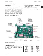
The PWM board times out in Program
Mode after approximately 5-6 minutes
and will need to be reset by pushing the
reset button. If more time is needed to
verify correct airflow, perform the STORE
operation (through switch 8) after adjust-
ment to save the adjusted fan speed.
6. Determine desired fan operating points. Refer to
the Fan Calibration Curve label supplied on the
side of the equipment. There are two different
styles of Fan Calibration Curve, depending on EC
motor type.
The Fan Calibration Curve provided with
the unit represents response for a unit
with typical configuration. Actual airflow
may vary slightly depending on actual
system configuration.
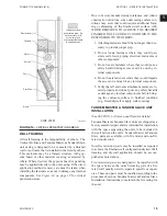
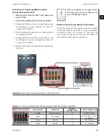
a. Constant RPM EC Motor. Refer to
Figure 14
on page 27
for sample label. Five curves
are shown, showing factory default airflow
for Minimum, Low, Medium, High, and
Maximum speeds. A table is provided which
shows the expected voltage across test points
TP1 and TP3 for each speed, depending on
whether the unit is set up for three speed or
2 – 10 VDC motor control.
b. b. Constant Airflow or Constant Torque EC
Motor. Refer to
Figure 15 on page 27
for
sample label. Several curves are shown on
the label, one for each size unit. Refer to the
0 to 2.5 volt scale on the label and use the
voltmeter to read the voltage across TP1 and
TP3 to determine desired airflow setting.
Changing the factory setting for minimum
and maximum CFMs will invalidate the
range for the Fan Calibration Curve as it
will narrow the scale of the input signal.
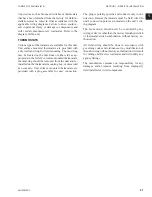
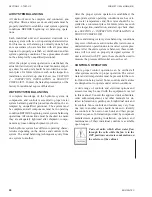
7. Follow instructions for adjusting EC motor speed
using the G3 PWM board. Separate instructions
are provided for Three Speed (adjustable) and 2 –
10 VDC Proportional motor control modes.
LD19222
2-10V Manual
Max
High
Medium
Low
Min
10.0 VDC
7.5 VDC
6.0 VDC
4.0 VDC
2.0 VDC
0.88 VDC
0.70 VDC
0.53 VDC
0.35 VDC
0.18 VDC
Max
High
Medium
Low
Min
0
100
200
300
400
500
600
700
Airflow (SCFM)
0.50
0.45
0.40
0.35
0.30
0.25
0.20
0.15
0.10
0.05
0.00
ESP
(inches w
.g.)
HORIZONTAL LOW PROFIL PLENUM SIZE 30 FAN CALIBRATION CURVE:
CONSTANT-RPM EC MOTOR
3 Row, 10 FPI, 1” Throwaway filter
FIGURE 14 -
CONSTANT RPM AND CONSTANT
TORQUE EC MOTORS EXAMPLE FAN
CALIBRATION CURVE
2.0
6.8
5.2
8.4
10.0
2.8
9.2
7.6
6.0
4.4
3.6
LD19223
Remote Analog Adjustment Voltage (VDC)
2000
200
400
600
800
1000
1200
1400
1600
1800
0
Airflow (CFM)
0.00
2.25
2.00
1.75
1.50
1.25
1.00
0.75
0.50
0.25
2.50
HORIZONTAL LOW PROFILE PLENUM
FAN CALIBRATION CURVE: CONSTANT-CFM EC MOTOR
Manual Adjustment Voltage (VDC)
60
50
40
20
30
25
FIGURE 15 -
CONSTANT AIRFLOW AND
CONSTANT TORQUE EC MOTORS EXAMPLE FAN
CALIBRATION CURVE
Adjusting EC Motor Speed
This section contains instructions for using the G3
PWM board to adjust the EC motor speed for balanc-
ing purposes. There are two modes of EC motor speed
control: Three Speed operation at three fixed (adjust-
able) speeds, or Proportional Control with remote 2 –
10 VDC signal.
For units with electric heat, fan speed
must not be adjusted below 70 CFM/kW.
Summary of Contents for VHA
Page 10: ...ENVIRO TEC 10 FORM ET115 24 NOM4 819 THIS PAGE INTENTIONALLY LEFT BLANK ...
Page 41: ...ENVIRO TEC 41 SECTION 2 START UP FORM ET115 24 NOM4 819 THIS PAGE INTENTIONALLY LEFT BLANK ...
Page 54: ...ENVIRO TEC 54 FORM ET115 24 NOM4 819 SECTION 6 Dimensional Data 74 80083 ...
Page 78: ...ENVIRO TEC 78 FORM ET115 24 NOM4 819 SECTION 6 Dimensional Data NOTES ...

