ENVIRO-TEC
12
FORM ET115.24-NOM4 (819)
SECTION 1 - RECEIPT & INSTALLATION
HANDLING & INSTALLATION
While all equipment is designed and fabricated of
sturdy construction and may present a rugged appear-
ance, great care must be taken to assure that no force
or pressure be applied to the coil, risers, piping or drain
stub-outs during handling. Do not use the risers for lift-
ing the unit. Also, depending on the options and acces-
sories, some units could contain delicate components
that may be damaged by improper handling. Wherever
possible, all units should be maintained in an upright
position and handled by the exterior casing, with no
impact forces applied that may damage internal com-
ponents or painted surfaces.
The equipment covered in this manual IS NOT suit-
able for outdoor installations. The equipment should
never be stored or installed where it may be subjected
to a hostile environment such as rain, snow, extreme
temperatures, or hazardous chemicals.
During and after installation, special care must be tak-
en to prevent foreign material such as paint, plaster,
and drywall dust from being deposited in the drain pan,
electric heater, motor and blower wheels. Failure to do
so may have serious adverse effects on unit operation
and in the case of the heater, motor and blower assem-
bly, may result in immediate or premature failure. All
manufacturers’ warranties are void if foreign material
is allowed to be deposited on the heater, motor or blow-
er wheels of any unit. Some units and/or job conditions
may require some form of temporary covering during
construction.
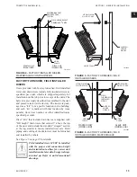
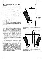
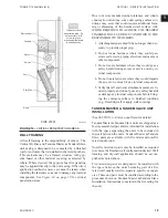
Condensate pan is internally sloped toward drain con-
nection. Make assurance that unit is level and plumb.
Level the unit to insure proper coil operation and con-
densate drainage. After units are positioned and risers
centered in pipe chase, plumb the unit in two directions,
using unit casing as a reference. Avoid any interference
with wiring, coil, or coil connections, drain pain, and
structural components inside the cabinet while using
bolts or lag screws to anchor the unit to building. See
Figure 10 on page 19
for critical penetration areas.
After mounting the unit, it is then ready for the various
service connections such as water, drain and electri-
cal. At this time it should be verified that the proper
types of service are actually provided to the unit. On
those units requiring chilled water and/or hot water,
the proper line size and water temperature should be
available to the unit. The electrical service to the unit
should be compared to the unit nameplate to verify
compatibility. The routing and sizing of all piping,
and the type and sizing of all wiring and other elec-
trical components such as circuit breakers, disconnect
switches, etc. should be determined by the individual
job requirements and should not be based on the size
and/or type of connection provided on the equipment.
All installations should be made in compliance with all
governing codes and ordinances. Compliance with all
codes is the responsibility of the installing contractor.
Any new field connections must ensure all openings
are sealed and properly insulated. Improper sealing
or insulation can result in untreated air infiltrating the
unit. Units are not internally thermally isolated, proper
thermal breaks required at installation to prevent ad-
verse effects.
For seismic certified installation, refer
-
ence the seismic installation document.
COOLING/HEATING MEDIUM CONNECTIONS
Toxic residues and loose particles result-
ing from manufacturing and field piping
techniques such as joint compounds,
soldering flux, and metal shavings may be
present in the unit and the piping system.
Special consideration must be given to
system cleanliness when connecting to
solar, domestic or potable water systems.
Submittals and Product Catalogs detailing unit opera-
tion, controls, and connections should be thoroughly
reviewed BEFORE beginning the connection of the
various cooling and/or heating mediums to the unit.
All accessory valve packages should be installed as re-
quired, and all service valves should be checked for
proper operation.
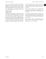
If coil and valve package connections are made with
“sweat” or solder joint, care should be taken to assure
that no components in the valve package are subjected
to a high temperature which may damage seals or other
materials. Many two-position electric control valves,
depending on valve operation, are provided with a
manual-opening lever. This lever should be placed in
the “open” position during all soldering or brazing op-
erations. Solder joints with Sil-fos
®
, phos-copper, or
similar high temperature alloy. Do not use soft solder.
Summary of Contents for VHA
Page 10: ...ENVIRO TEC 10 FORM ET115 24 NOM4 819 THIS PAGE INTENTIONALLY LEFT BLANK ...
Page 41: ...ENVIRO TEC 41 SECTION 2 START UP FORM ET115 24 NOM4 819 THIS PAGE INTENTIONALLY LEFT BLANK ...
Page 54: ...ENVIRO TEC 54 FORM ET115 24 NOM4 819 SECTION 6 Dimensional Data 74 80083 ...
Page 78: ...ENVIRO TEC 78 FORM ET115 24 NOM4 819 SECTION 6 Dimensional Data NOTES ...


