


24
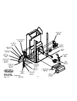
The following is a list of electrical components and their functions on the ENVIROFIRE EF-V EVOLUTION
pellet stove.
1
POWER CORD OUTLET.
Main power supply to the unit supplied at this location.
2
CONVECTION BLOWER.
This blower fan, (mounted in the center bottom of the unit) draws room air from the back of the stove and passes
the air through the heat exchanger tubes and back into the room. The sealed system keeps the room air separate
from the combustion air. The convection blower’s fan controller controls the fan’s speed.
3
START-UP TIMER.
This 15 minute one shot timer, by-passes the 120
°
F (49
°
C) temperature sensor allowing the unit to operate when
cold. The timing cycle is initiated by pressing the start-up switch. The 15 minute timer is located right under the
timing control module on the right side pillar. The unit is also responsible for initiating the ignition cycle.
4
TIMING CONTROL MODULE.
The timing control module is mounted in the middle, on the right rear pillar of the unit. This module controls the
switching power of the auger motor. The module’s switching duty cycle is controlled by the Dial-A-Fire.
5
AUGER MOTOR.
This 1RPM motor is responsible for turning the auger, which in turn transports pellets to be dropped into the burn
pot liner. The auger motor’s control is handled by the timing control module and Dial-A-Fire.
6
COMBUSTION/EXHAUST PHASE CONTROLLER (Blower speed control module).
The phase controller supplies an adjustable voltage to the combustion blower. The voltage controls the blower’s
speed. The module is controlled by the potentiometer in the Dial-A-Fire. As the feed rate is increased, the
blower’s speed is increased proportionally.
7
IGNITER.
This is a heating element used to ignite the fuel. When the pellet stove is started, the igniter is energized. Air
passes through the igniter tube over the igniter. The air becomes super heated, drying the pellet fuel and then
igniting the pellets through convection. The igniter is located in the center of the firebox next the air inlet tube.
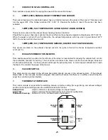
8
DIAL-A-FIRE (Heat output knob).
This unit is responsible for controlling the timing of the auger motor. When turned clockwise it will cause the OFF
time between auger pulses to shorten. Resulting in more heat output and pellet consumption. Turn the knob
counter-clockwise and the reverse will happen. When this knob is turned fully counter-clockwise past the click, the
auger motor will be turned off. This component also controls the exhaust blower speed via the PHASE
CONTROLLER.
9
START-UP SWITCH.
When the momentary contact switch is pressed it will initiate the 15 minute Start-Up Timer including the igniter.
10
AUGER PULSE LIGHT.
This light will flash in conjunction with the pulses to the auger.
Summary of Contents for EF-V EVOLUTION
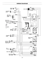
Page 30: ...30 WIRING DIAGRAM...


