


Connecting to the Network
3-14 Installation
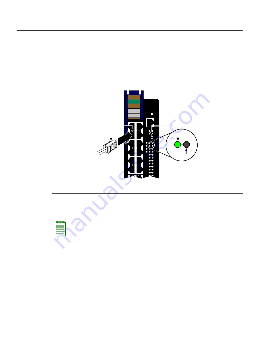
To
connect
and
verify
UTP
cable
connections
to
RJ45
ports
1
through
48,
refer
to
Figure 3
‐
4
and
proceed
as
follows:
1.
Ensure
that
the
device
connected
to
the
other
end
of
the
segment
is
powered
ON.
2.
Insert
the
RJ45
connector
on
the
twisted
pair
segment
into
the
appropriate
RJ45
port
connector.
3.
Verify
that
a
link
exists
by
checking
that
the
port
RX
(Receive)
LED
is
ON
(flashing
amber,
blinking
green,
or
solid
green).
If
the
RX
LED
is
OFF
and
the
TX
(Transmit)
LED
is
not
blinking
amber,
perform
the
following
steps
until
it
is
on:
a.
To
view
the
receive
and
transmit
activity
on
a
group
of
segments,
press
the
GROUP
SELECT
button
for
less
than
one
second
(see
Figure 3
‐
4
)
to
step
to
the
group
of
interest
(Groups
1
through
4).
b. Each
time
the
GROUP
SELECT
button
is
pressed
for
less
that
one
second,
the
GROUP
LED
lights
up
in
sequence,
indicating
which
Group
is
selected.
The
receive
and
transmit
activity
for
that
group
of
segments
is
then
indicated
by
the
RX
and
TX
LEDs
for
each
segment.
Figure 3-4 Connecting a Twisted Pair Segment with RJ45 Connector
1
RJ45 cable connector
2
RJ45 port connector
3
GROUP SELECT button
Note:
If the RX and TX LEDs of a port do not indicate a link and the end-point device is a
PD, you may have a port without 48 Vdc to operate the PD. To check the PoE Port Status,
refer to
“Verifying PoE Port Status”
on page 3-17.
1
2
3
4
1X
G
R
O
U
P
1
11X
OFFLINE/
RESET
COM
CPU
MGMT
GROUP
SELECT
GROUP
1
2
3
4
5
6
7
8
9
10
11
12
POE
12 X
1
2
3
4
4H4285-49
FAST ENET
RX
TX
À
Á
Â
Summary of Contents for 6H308-48
Page 2: ......
Page 12: ...x...
Page 16: ...xiv...
Page 56: ...Completing the Installation 3 28 Installation...
Page 70: ...Regulatory Compliance A 4 Specifications...
Page 88: ...PoE Port Status LEDs C 4 About PoE Power over Ethernet...


