background image

Terms and Conditions

xii

Entek IRD 6600 Series Protection Monitors

Summary of Contents for 6682

Page 1: ...soute Shell Expansion Monitor Your Guide to the 6687 Protection Monitor Entek IRD International Corporation P N 45171 H L P L I T D I S R E S T S T S E L 6687 CASE EXPANSION MONITOR CHAN 1 CHAN 2 D A 500 0 mil D A A D A D ...

Page 2: ...copied or reproduced or transmitted in any form whatever including orally or by electronic transmission nor is any information in this Manual to be disclosed in any form whatever including orally or by electronic transmission to anyone other than an authorized representative of the User s employer who also shall agree not to disclose same without express prior written consent of Entek IRD Internat...

Page 3: ...sages 7 Installation 8 Monitor Backplane 8 LVDT to Monitor Wiring 9 Non contact Sensor to Monitor Wiring 11 Configuration 12 General Configuration Instructions 12 User Menu Configuration 14 To display the User menu 14 User menu options 15 User menu structure 15 To set the date and time 16 ALARMS submenu 17 Factory Menu Configuration 18 To display the Factory menu 18 Factory menu options 18 Factory...

Page 4: ...687 Protection Monitor Table of Contents Testing Calibration and Relays 26 Signal Inputs for Testing 26 Calibration and System OK Relay Test 28 Alarm Relay Test 29 Specifications 31 6687 Monitor Settings Worksheet 34 ...

Page 5: ...pecification or order will be effective unless specifically approved in writing by an authorized officer of Entek IRD In any event delivery shipping and service dates are always quoted subject to unavoidable delays due to causes beyond Entek IRD s control including but not limited to strikes casualty war acts of God systems failure or government action 4 TERMS Payment terms for domestic orders are...

Page 6: ...ervices will be free from defects in workmanship under normal conditions for 90 days from performance With respect to performance related in any way to the passage of time to the year 2000 and beyond or the occurrence of a leap year Entek IRD does not make any representation or warranty Entek IRD has issued a Year 2000 readiness disclosure statement which is available to Customer upon request B Wi...

Page 7: ...tion accrues 11 TITLE AND LIEN RIGHTS Each product shall remain personal property regardless of how it is affixed to Customer s real property and Entek IRD reserves a purchase money security interest in the product until the purchase price has been fully paid Customer agrees to execute and hereby appoints Entek IRD as its attorney in fact to execute on Customer s behalf any documents requested by ...

Page 8: ... the Software provided is for a wide area network WAN multi user system as identified in the quotation Customer may install the Software on a single database server and may access the Software only from network clients at the same site and at the number of remote sites for which Customer purchases licenses If the Software provided is for a multi user system as identified in the quotation the Custo...

Page 9: ...with the specifications provided by Entek IRD in the product manual of such Software for a period of one year from the date of shipment With respect to performance related in any way to the passage of time to the year 2000 and beyond or the occurrence of a leap year Entek IRD does not make any representation or warranty Entek IRD has issued a Year 2000 readiness disclosure statement which is avail...

Page 10: ...or programs not furnished by Entek IRD or in other than the specified operating environment This Section states Entek IRD s entire obligation to Customer regarding infringement or the like 4 EXCLUSIVE REMEDIES AND LIABILITY LIMITATION THE REMEDIES PROVIDED HEREIN ARE CUSTOMER S SOLE AND EXCLUSIVE REMEDIES AND ENTEK IRD S EXCLUSIVE LIABILITY WHETHER ARISING IN CONTRACT TORT INCLUDING NEGLIGENCE STR...

Page 11: ...er made by the parties or their representatives No statement purporting to modify any of these terms or conditions shall be binding unless expressly agreed to in writing signed by an officer of Entek IRD and by Customer These terms and conditions and any issue claim or dispute arising hereunder shall be interpreted under and governed in all respects by the internal laws of the State of Ohio and th...

Page 12: ...Terms and Conditions xii Entek IRD 6600 Series Protection Monitors ...

Page 13: ...e event of a Danger alarm or a first out Danger alarm message from another monitor the 6687 stores this data in a separate memory area A first out alarm is the first alarm in an interconnected series of monitors This feature allows later analysis of the data leading up to the event that caused the Danger alarm You can retrieve any of this data from the monitor using the MODBUS protocol through a 4...

Page 14: ...u current engineering unit for the monitor g g acceleration Hz Hertz frequency in ins inch inches mA milliamp mil thousandth of an inch mm millimeter mV millivolt pk peak signal detection pp peak to peak signal detection rms root mean square signal detection rot degrees of rotation RPM revolutions per minute frequency µm micrometer V Volt VAC Volt AC VDC Volt DC ...

Page 15: ...ach input channel The two channel connectors carry a buffered input signal at 25 of the input millivolt sensitivity H L P L I T D I S R E S T S T S E L 6687 CASE EXPANSION MONITOR CHAN 1 CHAN 2 D A 500 0 mil D A A D A D Retaining screw 4 HLP button reserved for future use LIT backlight button DIS display button SEL select button Up Arrow button Down Arrow button TST button reserved for future use ...

Page 16: ... Danger for each channel these lines signal connected monitors of an alarm condition applying common first out alarm indications across the monitors In the case of a Danger alarm this causes all connected monitors to store their trip trend and trip spectrum data for later analysis z Transducer power supply at 18 VDC 18 VDC 24 VDC or 24 VDC HLP Reserved for future use LIT Toggles the display backli...

Page 17: ...partment Basic Operation This section describes the day to day operations for the 6687 protection monitor It includes the steps to use the display backlight display alternate pages reset the relays after an alarm if the alarm relays are set to latching and display the firmware version It also describes the status messages that may appear on the display Display Backlight The backlight makes it easy...

Page 18: ...g the Monitor Firmware Version The behavior of a 6600 Series protection monitor is controlled by an internal firmware program This firmware program has a version number just like a software program The version number may be useful in diagnosing problems with your monitor should any arise Note that the monitor number in the display is the 6682 which is correct because the 6682 and 6687 share the sa...

Page 19: ... goes out of the specified range The number indicates the channel with the transducer fault See the manual on 6600 monitor troubleshooting for diagnostic information This message appears when the position exceeds one of the Alert alarm setpoints The number indicates the channel that exceeded the Alert alarm setpoint The underline indicates that the channel was the first out alarm for this monitor ...

Page 20: ...AN 2 9 NOT USED 10 REMOTE RESET 11 START UP INHIBIT 12 RESERVED 13 NOT USED 14 NOT USED 15 NOT USED 16 FIRST OUT ALERT 17 FIRST OUT DANGER 18 MON SER I O RX 19 MON SER I O RX 20 MON SER I O TX 21 MON SER I O TX 22 24V DC POWER A 23 24V DC POWER B 24 24V RETURN POWER CONVENTION PIN 1 LINE PIN 2 NEUTRAL PIN 3 EARTH 9 PIN D CONNECTOR PIN 1 NOT USED PIN 2 NOT USED PIN 3 NOT USED PIN 4 MON SER I O TX P...

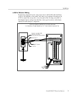
Page 21: ...This diagram shows a configuration that allows a more positive reading on the display upscale when the plunger is compressed 16 18 19 24 23 20 21 22 17 7 10 15 11 12 13 14 9 8 2 6 4 5 3 1 EARTH NEUTRAL LINE 43 44 48 45 46 47 32 42 35 38 41 40 39 36 37 34 33 31 29 30 27 28 26 25 Channel 1 Input Signal TYPICAL WIRING FOR MODEL 15383 LINEAR VARIABLE DIFFERENTIAL TRANSFORMER LVDT TO 6600 VIBRATION MON...

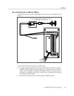
Page 22: ...configuration of the power supply refer to the manual on 6600 monitor power supplies and backplanes z You may ground the cable shield at either end of the cable Do not ground the shield at both ends 16 18 19 24 23 20 21 22 17 7 10 15 11 12 13 14 9 8 2 6 4 5 3 1 EARTH NEUTRAL LINE 43 44 48 45 46 47 32 42 35 38 41 40 39 36 37 34 33 31 29 30 27 28 26 25 Channel 1 Input Signal TYPICAL WIRING FOR MODEL...

Page 23: ...ured to provide negative voltage The power supply is configured with jumpers on the power supply For more information on configuration of the power supply refer to the manual on 6600 monitor power supplies and backplanes z Ground the cable shield as shown Do not ground the shield at both ends 16 18 19 24 23 20 21 22 17 7 10 15 11 12 13 14 9 8 2 6 4 5 3 1 EARTH NEUTRAL LINE 43 44 48 45 46 47 32 42 ...

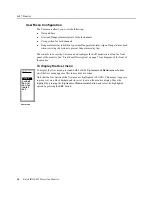
Page 24: ...ight the desired option 3 Press the SEL button to display the screen where you change the value for the option 4 Use the Arrow buttons to change the value 5 Press the SEL button to return to the menu For both the User and Factory menus the monitor remembers any changes you make but does not write them to memory until you exit the User or Factory menu Note If the current value does not change when ...

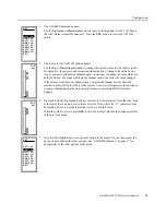
Page 25: ...monitor is protected by the link security feature Contact your Supervisor for assistance For more information on the link security feature contact Entek IRD Customer Support 4 Press and hold the Up Arrow button to increase the Alert setpoint Note that the value at the top of the screen gives you the exact Alert value while the A indicator on the bar graph gives you a visual indication relative to ...

Page 26: ...monitor are all on the front panel of the monitor See Front Panel Description on page 3 for a diagram of the front of the monitor To display the User menu To display the User menu press and hold both the Up Arrow and Down Arrow buttons until the User menu appears This takes about 4 seconds Note that the first option of the User menu is highlighted CLOCK This means it appears in green text on a bla...

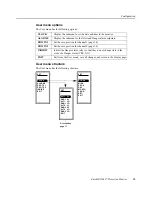
Page 27: ...alarm setpoints ZRO TX1 Set the zero position for channel 1 page 24 ZRO TX2 Set the zero position for channel 2 page 24 INHIBIT Inhibit the Danger alarm relays so that they do not change state in the event of a Danger alarm YES NO EXIT Exit from the User menu save all changes and return to the display page ALARMS ZRO TX1 ZRO TX2 INHIBIT EXIT CLOCK SET MINS SECS DAY MONTH YEAR SET EXIT HOURS SET DN...

Page 28: ...or PM Press SEL to save the current value for the option and return to the CLOCK menu 4 Note that the highlight moves to the next option in the menu Repeat the above steps to change the other options in the CLOCK submenu Note that the monitor does not set each of the options to the current date and time before you start For that reason you must make sure all the options are set correctly 5 For the...

Page 29: ...T1 HI Choose the high Alert alarm setpoint for input channel 1 999 99 to 9999 99 DNG1 HI Choose the high Danger alarm setpoint for input channel 1 999 99 to 9999 99 ALT1 LO Choose the low Alert alarm setpoint for input channel 1 999 99 to 9999 99 DNG1 LO Choose the low Danger alarm setpoint for input channel 1 999 99 to 9999 99 ALT2 HI Choose the high Alert alarm setpoint for input channel 2 999 9...

Page 30: ...on the monitor display Move the highlight by pressing the Up Arrow or Down Arrow button and select the highlighted option by pressing the SEL button Factory menu options The Factory menu has the following options Note If you configure the 6687 to use only one channel CHANS 1 make the following adjustments to avoid alarm or transducer failure messages on channel 2 z Set the Alert and Danger alarms ...

Page 31: ... CHANS EXIT COMM S SET BAUD PARITY RESCALE SCALE EXIT MODULE SET LATCHED YES DELAYS EXIT SET FAILSAFE A D TX1 SNS FS LO 1 FS HI 1 UNITS 2 TX2 SNS FS LO 2 FS HI 2 EXIT UNITS 1 SET TX HI 1 TX LO 2 TX HI 2 EXIT TX LO 1 SET STARTUP 1 0 SECS EXIT SET GLOBAL 1 0 SECS Described on page 24 Described on page 22 Described on page 22 Described on page 21 Described on page 20 Described on page 18 ...

Page 32: ...nications NONE EVEN RESCALE Choose the format for data transmission NO 16 BIT Some MODBUS masters handle data as integer numbers not floating point format NO uses floating point format while 16 BIT uses integer unsigned format SCALE Choose the scale for 16 BIT data transmission 0 65535 if the MODBUS master uses integer 16 BIT numbers This sets the value to transmit for full scale amplitude Use the...

Page 33: ...S HI 1 Choose the full scale value for the monitor for channel 1 0 to the maximum value in transducer input units This also sets the display full scale and the 20 mA point for the 4 20 mA outputs This options works with the TX1 SNS option See the note below the table UNITS 2 Choose the native transducer and display units mil mm µm ins rot for channel 2 TX2 SNS Choose the transducer sensitivity in ...

Page 34: ... 00 to 23 00 volts TX HI 2 Choose the most positive acceptable transducer voltage for channel 2 23 00 to 24 00 volts EXIT Return to the Factory menu The monitor remembers the current values for menu options but does not write them to memory until you exit the Factory menu LATCHED YES DELAYS EXIT SET FAILSAFE A D Factory menu RELAYS FAILSAFE Choose failsafe or nonfailsafe operation for the alarm re...

Page 35: ...th power applied to the unit conditions the relay closes the circuit between the common and the N O normally open terminals z Under alarm or loss of power conditions the relay changes state to close the circuit between the common and N C normally closed terminals The following are true of a relay in nonfailsafe condition z The relay is not energized when power is applied to the unit z The relay in...

Page 36: ...d FS HI on the RANGES menu to match the monitoring requirements See RANGES submenu on page 21 For this illustration you would set FS LO 1 to 0 mils and set FS HI 1 to 1000 0 mils 3 Exit from the Factory menu The display may show a solid bar for the channel instead of showing the case at the zero cold position 4 Choose ZRO TX1 from the User menu You can ignore the line that changes length on this s...

Page 37: ... Keep pressing and releasing the Arrow button until the indicator comes within the display scale Then carefully adjust the display until the indicator displays zero both on the bar and the digital value Note that zero is at the bottom of the scale for this example 6 Choose ALARMS from the User menu ALARMS submenu on page 17 If LO alarms are not needed for your application set the LO alarm levels b...

Page 38: ...tions are from the RANGES page 21 and TX OK submenus page 22 Full scale LO value FS LO 1 ________________ Full scale HI value FS HI 1 ________________ Voltage at FS HI ________________ Voltage at FS LO ________________ TX Voltage low TX LO 1 ________________ TX Voltage high TX HI 1 ________________ Zero position ________________ The zero position is the cold case position This calibration procedur...

Page 39: ...ons for testing 6600 protection monitors Note 1 Transducers may be simulated directly at the backplane as shown or elsewhere If this involves application via barriers ensure that the barrier rating is not accidentally exceeded 2 Verify the DC source voltage with a DVM at the monitor terminal strip TYPICAL SIGNAL INPUTS FOR TESTING 6687 TWO CHANNEL MONITOR 6687 TERMINALS 1 AND OR 3 SIGNAL INPUT 2 C...

Page 40: ... Look at the multimeter attached to the 4 20 mA recorder terminals The meter should read 4 mA 4 5 of full scale 6 Increase the DC voltage input to the voltage at FS HI 7 Look at the 6687 front panel display and note the digital value for channel 1 It should be the same as the FS HI setting 2 5 of full scale 8 Look at the multimeter attached to the 4 20 mA recorder terminals The meter should read 2...

Page 41: ... should test both sets of alarms for each channel if you are using them Note If the LATCHED option is set to YES you may have to manually reset the relays by pressing the RES button on the front panel of the monitor The LATCHED option is on the RELAYS submenu page 22 The relay contacts on the backplane of the 6687 are Transducer type LVDT 15383 Transducer native units UNITS 1 mil Transducer sensit...

Page 42: ...on on the front panel of the monitor 5 Test the state of the channel 1 Alert relay terminals open or closed The state should change when the input signal exceeds the HI Alert setpoint Depending on the GLOBAL option setting in the DELAYS submenu page 24 it may take up to 30 seconds before the relay changes state 6 Adjust the input voltage until the measurement value goes above the channel 1 HI Dang...

Page 43: ...el BNC connectors actively buffered input signal output signal and attenuated by a factor of 4 Output impedance 270 ohms Serial data Per monitor 4 wire RS 422 485 for output to host computer PLC or DCS distributed control system MODBUS RTU protocol Baud Rate 4800 9600 19200 38400 Data transferred From serial port overall amplitude relay status 30 minute trend 1 minute interval 30 minute trend prio...

Page 44: ...ule System OK 1 Alert relay per channel 2 Danger relays per channel Programming Per monitor user configured for normally energized failsafe normally de energized nonfailsafe latching nonlatching time delay Reset Relays respond to the RES button on the front panel as well as remote relay reset signal through backplane terminals Contact rating 5 A 120 VAC 50 60 Hz 5 A 30 VDC requires a minimum curre...

Page 45: ...2 13 W typical 14 W maximum 230 VAC power 13 14 W typical 16 W maximum Physical attributes Dimensions 15 inches long 5 75 inches high 2 44 inches wide 27 9 cm long 14 6 cm high 6 19 cm wide Weight 1 45 kg monitor power supply and backplane Environmental Operating temperature Normal operating range 4 F to 131 F 20 C to 55 C Storage temperature Storage 4 F to 167 F 20 C to 75 C Relative humidity 0 t...

Page 46: ... future reference Menu Option Range Setting Date Notes User menu CLOCK ALARMS submenu ALT1 HI 999 99 to 9999 99 DNG1 HI 999 99 to 9999 99 ALT1 LO 999 99 to 9999 99 DNG1 LO 999 99 to 9999 99 ALT2 HI 999 99 to 9999 99 DNG2 HI 999 99 to 9999 99 ALT2 LO 999 99 to 9999 99 DNG2 LO 999 99 to 9999 99 ZRO TX1 ZRO TX2 INHIBIT YES NO Factory menu COMM S submenu MODULE 1 to 247 BAUD 4800 to 38400 PARITY NONE ...

Page 47: ...TX OK submenu TX LO 1 24 00 to 23 00 V TX HI 1 23 00 to 24 00 V TX LO 2 24 00 to 23 00 V TX HI 2 23 00 to 24 00 V RELAYS submenu FAILSAFE AD D A NO LATCHED YES NO DELAYS submenu GLOBAL 0 0 to 30 0 sec STARTUP 0 0 to 30 0 sec CHANS 1 2 Menu Option Range Setting Date Notes ...

Page 48: ...36 Entek IRD 6687 Protection Monitor 6687 Monitor ...

Page 49: ...1 LO option 17 DNG2 HI option 17 DNG2 LO option 17 Alert alarm indicator 3 setpoint 17 See also alarms ALERT message 7 ALT1 HI menu option 17 ALT1 LO menu option 17 ALT2 HI menu option 17 ALT2 LO menu option 17 alternate display pages 6 applications 1 B backlight 5 7 backplane terminal diagram 8 basic operation 5 BAUD menu option 20 BNC connectors 3 buttons descriptions 4 DIS 4 6 Down Arrow 4 12 H...

Page 50: ...iguring 18 description 12 displaying 18 options 18 structure 19 Factory menu options CHANS 18 COMM S 18 RANGES 18 RELAYS 18 TX OK 18 Factory menu submenus COMM S 20 DELAYS 24 RANGES 21 RELAYS 22 TX OK 22 FAILSAFE menu option 22 failsafe operation 23 firmware version 6 front panel description 3 FS HI 1 menu option 21 FS HI 2 menu option 21 FS LO 1 menu option 21 FS LO 2 menu option 21 full scale di...

Page 51: ...2 option 21 FS LO 1 option 21 FS LO 2 option 21 TX1 SNS option 21 TX2 SNS option 21 UNITS 1 option 21 UNITS 2 option 21 relays failsafe operation 23 inhibit 15 24 normally closed N C 23 normally open N O 23 resetting 6 specifications 32 testing alarm relays 29 testing System OK relay 28 testing input signal 26 RELAYS menu option 18 RELAYS submenu DELAYS option 22 description 22 FAILSAFE option 22 ...

Page 52: ...on 22 TX LO 1 menu option 22 TX LO 2 menu option 22 TX OK menu option 18 TX OK submenu description 22 TX HI 1 option 22 TX HI 2 option 22 TX L0 1 option 22 TX L0 2 option 22 TX1 SNS menu option 21 TX2 SNS menu option 21 U UNITS 1 menu option 21 UNITS 2 menu option 21 Up Arrow button 4 12 User menu ALARMS submenu 17 CLOCK submenu 16 configuring 14 description 12 displaying 14 options 15 structure 1...

Reviews: