INVUE GV148 LIQUID CHEMICAL CONCENTRATION MONITOR
25
User Guide | Entegris, Inc.
COMMUNICATION COMMAND SET
—
Contact Entegris to obtain a copy of the communica-
tions specification if you plan to communicate with
the device using RS422/485 protocol.
MAINTENANCE
—
The GV148 concentration monitor is designed with a
cleaning port for easy access to the sensor window
without sensor removal.
WARNING: Failure to maintain cleanliness of the
sensor window will create errors in the reported IoR.
Ideally, DI water is used as the reference chemical
and if it does not produce the intended IoR (1.333000),
the window may need to be cleaned. Even exposure
to DI water could result in window contamination
over time.
MANUAL WINDOW CLEANING METHOD
WARNING: It is recommended that an Entegris
Bottom Cap Removal Tool (part number
GV148CPTOOL) and a ¼" hex drive torque
wrench (1.8 N•m [16 in•lb]) be used when
cleaning the window.
This
demonstrates how to properly remove
the port, manually clean the sapphire window,
and reassemble the port after manual cleaning is
completed.
AUTOMATED IN SITU WINDOW CLEANING METHOD
Periodic window cleaning may be required to maintain
refractive index accuracies when certain chemistries
or CMP slurries are being monitored. The in situ clean-
ing nozzle takes the place of the bottom cap and
cleaning plug located on the bottom of the GV148
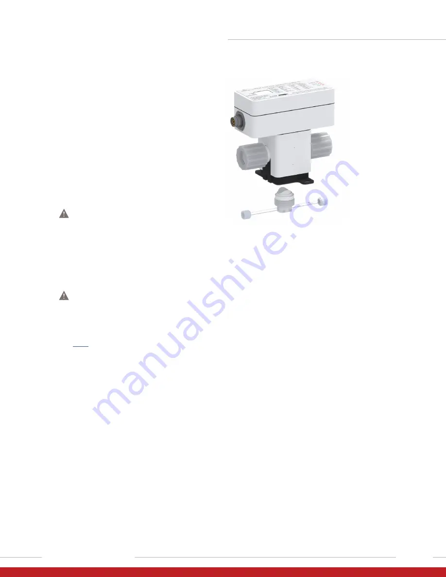
monitor. Figure 1 displays an exploded view of the
GV148 monitor with an in situ rinse nozzle.
Figure 1.
To implement a GV148 monitor with an in situ window
cleaner within a mix-blend station or slurry delivery
module, supplemental valving needs to be added to
the station external to the GV148 monitor.
On either side of the GV148 monitor, 3-way isolation
valves should be added to isolate the monitor from
the slurry flow stream. These isolation valves are
required to prevent dilution of the CMP slurry while
a window cleaning cycle is implemented. Figure 2
provides a schematic representation with valve states,
of a typical implementation when slurry is flowing
through the GV148 unit and being monitored. Figure 3
provides schematic representation with valve states,
of a typical implementation when an in situ window
clean is being implemented. The 3-way isolation
valves on either side of the GV148 monitor must be
½” orifice or larger, and the process lines going to
exhaust must be ½” or larger. When a window
cleaning cycle is implemented, both isolation valves
need to be toggled to the exhaust position enabling
a low resistance flow path for the atomized cleaning
solution to exit the GV148 monitor.


