


Quick
Start
Guide
www.ensembledesigns.com
Page 7
2. Click Authorize.
3. Click Done.
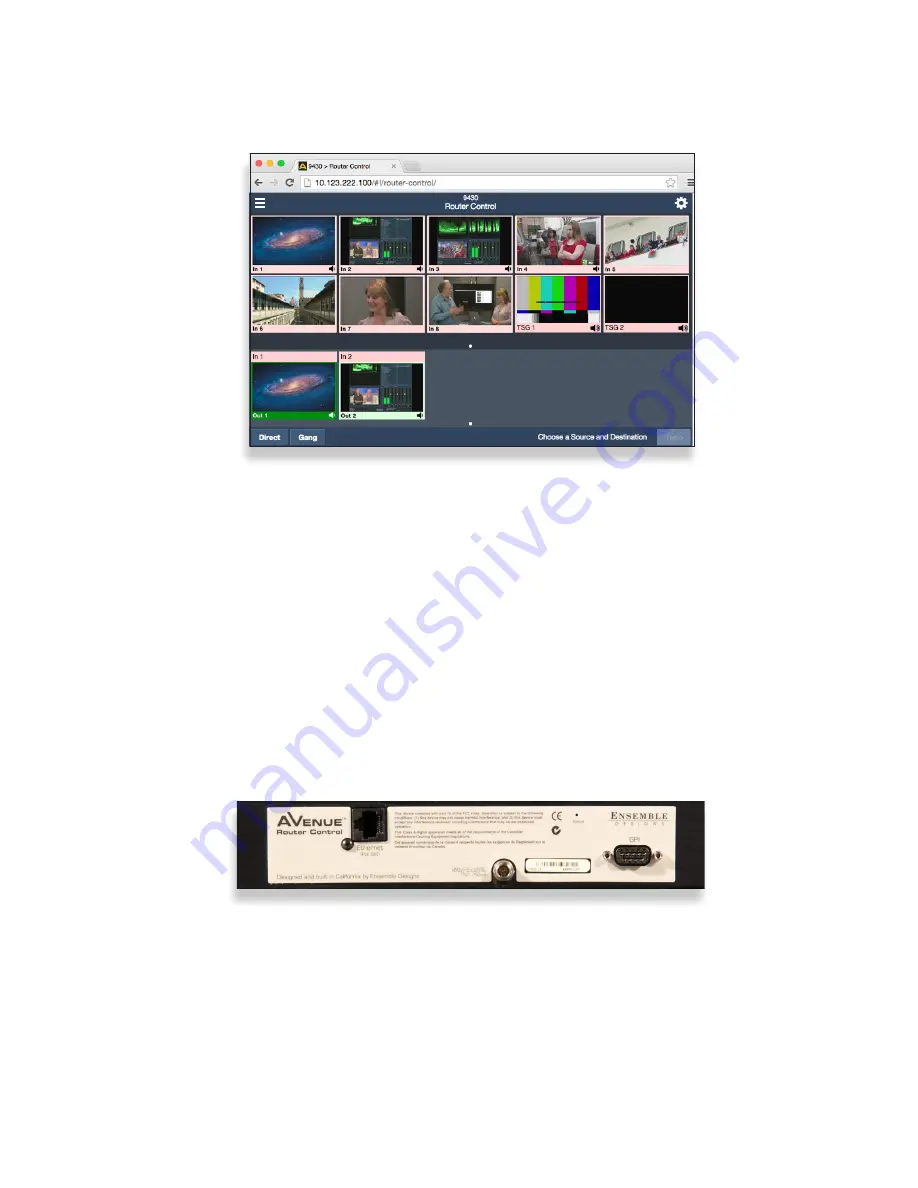
You are now presented with a Router control view with thumbnail icons. Without video
signals present, the thumbnails will indicate “No Input.” In the example below, however,
video signals were already connected to Router Inputs 1 - 8.
Step 4: Installing and Configuring the 5830 Router
Control Panel (Optional)
Connecting Ethernet Cable to RJ-45 Port
Make an Ethernet connection to the RJ-45 port on the rear of the Router Control Panel.
The Ethernet cable should be connected to a network Ethernet router or switch to make it
accessible to the Router.
A modular power supply is provided to power the Router Control Panel. Alternately, power
can be supplied by the Ethernet connection using PoE (Power over Ethernet), provided that
you have a PoE-enabled Ethernet switch to insert power into the Ethernet cables.
A portion of the rear of the 1RU Router Control Panel. Note the three connectors: the RJ-45
Port, the Power Input, and the 9-Pin GPI Connector
For a full explanation of creating custom profiles and configuring ports, see the “Model
9430 Installation, Configuration and Operations Guide” available through our website.
The 9430 Router control web interface showing video thumbnail images for 8 video
inputs (In 1 through In 8), 2 test signal generators named TSG 1 and TSG 2, and 2
destinations named Out 1 and Out 2. In this example, In 1 is being routed to Out 1 while
In 2 is being routed to Out 2.
Assigning an IP Address to the Router Control Panel
The 5830 Router Control Panel comes from the factory with the following default settings:
•
IP Address: 192.168.1.101
•
Subnet: 255.255.255.0