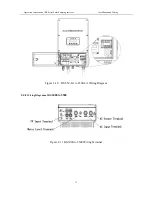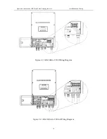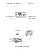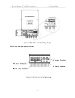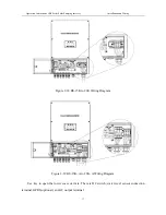
Operation Instruction of BS Series Solar Pumping Inverter Installation and Wiring
19
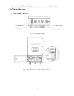
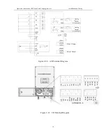
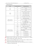
Terminal Introduction
Socket
Terminal Introduction
Wiring Introduction
DC
Input
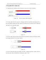
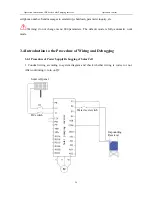
PV+
Connect with the positive pole of solar
array
PV-
Connect with the negative pole of solar
array
AC
Output
PE
Connect with protective ground wire
U
Connect with motor U phase
V
Connect with motor V phase
W
Connect with motor W phase
Water Level Sensor
Input (Switch Value)
+12V
Power supply of water level sensor
COM
Common signal grounding
S1
Auto power signal (factory settings have
been set)
S2
Water-full signal of water tower
(switching value)
S4
Water shortage signal of water
tower (switching value)
Water Level Sensor
Input (Analog Quantity)
+10V
Power supply of water level sensor
GND
Common signal ground wire
AI2
Water-full signal of water tower (analog
quantity)
AI3
Water shortage signal of water tower
(analog quantity)
RS485+
485 communication
RS485-
485 communication
CANAH
CAN communication
CANAL
CAN communication
Warning: the places of input sockets of DC positive pole and negative pole of different
models are different. Please confirm according to plug.
Warning: the signal marshalling sequence of AC output sockets of different models are
different. Please confirm according to the number on socket.
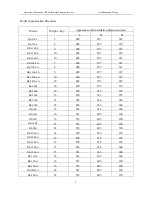
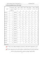
Warning: in order to guarantee that the system works normally, please select wire dimension
according to the following principle.

