8
NTD-4101
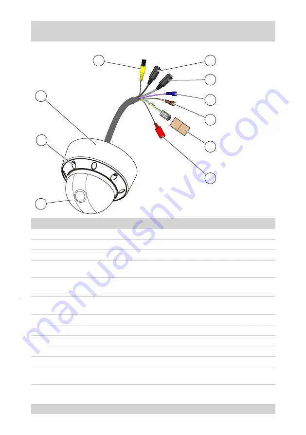
Design and connections of the camera
The following figure and the table describe the design and connecting elements of the camera:
2
1
6
7
5
9
10
8
4
No.
Designation
Function
Connection of
1
Dome cover
Housing part
-
2
Screwed connection
Dome cover attachment
-
Dome base
Dome with camera
-
4
VIDEO OUT
Video output, BNC
Monitor
Multiplexer
●
●
5
AUDIO IN
Audio input, .5-mm jack
connector, mono
Microphone
6
AUDIO OUT
Audio output, .5-mm jack
connector, mono
Active loudspeaker
Audio amplifier
●
●
7
ALARM IN
Purple:
Alarm input
Alarm contact
ALARM COMMON
Blue:
Alarm earth
Alarm contact
8
RS-485(+)
Black:
RS-485(+)
Non-inverted connection
RS-485(-)
Brown:
RS-485(-)
Inverted connection
9
LAN (RJ-45)
Network connection, RJ-45
Network cable
10
+12 VDC / GND
Power supply
Power supply unit 12 VDC, protection
class 2, 12 W
Summary of Contents for NTD-4101
Page 1: ...Operating Instructions 1 4 Network Colour Mini Dome Camera Model NTD 4101 ...
Page 2: ......
Page 4: ......
Page 47: ...47 NTD 4101 Dimensional Drawings Dimensions in mm ...
Page 51: ......


