soliphant II
FTM 30/31/32 DRLevel Limit Switch
Operating
I
nstructions
Hauser
+
Endress
Nothing beats know-how
BA 175F/00/en/08.98
Page 1: ...soliphant II FTM 30 31 32 DR Level Limit Switch Operating Instructions Hauser Endress Nothing beats know how BA 175F 00 en 08 98...
Page 2: ...AC power supply Electronic switch FEM 44 1 2 3 4 5 3 3 4 4 5 5 Min Max 3 4 5 3 4 5 B red red red Electronic insert FEM 44 for universal power supply Relay output with one potential free changeover co...
Page 3: ...g switching delay FEM 45 20 5 Electrical Connection 21 5 1 Wiring 21 5 2 Connection on site 24 6 Commissioning 27 6 1 Preparations 27 6 2 Function test 27 7 Maintenance 28 8 Troubleshooting and Repair...
Page 4: ...ment must be installed connected operated and maintained according to the instructions in this manual personnel must be authorized and suitably qualified The manual must have been read and understood...
Page 5: ...Devices located in and wiring entering areas with the designation explosion hazardous areas must conform with the stated type of protection Safe area non explosion hazardous area Symbol used in drawi...
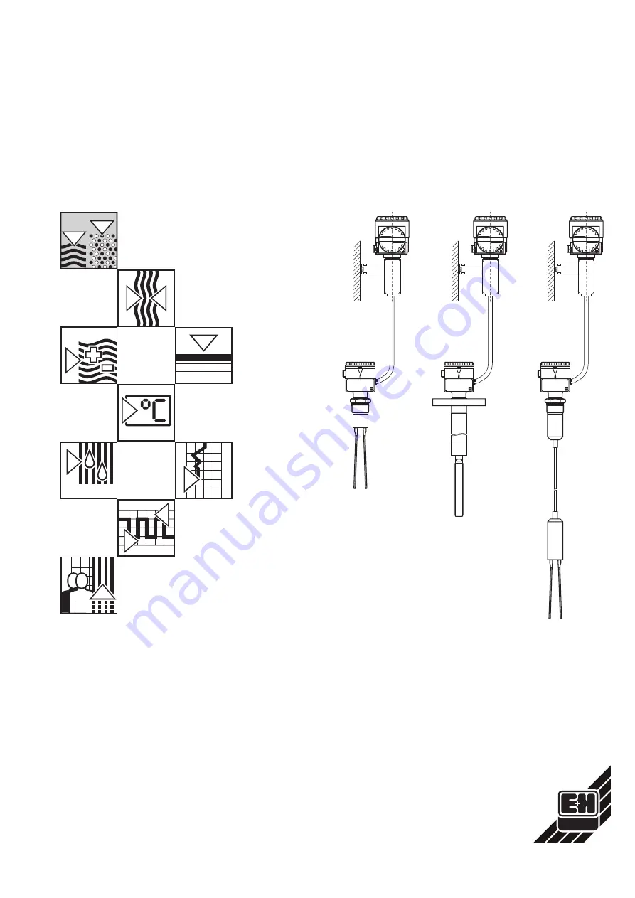
Page 6: ...t II FTM 30 DR compact sensor FTM 31 DR with extension tube FTM 32 DR with rope Separate housing with electronic insert FEM 41 for two wire alternating power supply FEM 44 for universal power supply a...
Page 7: ...onverted into a switching signal by the electronic insert in the separate housing Soliphant can be operated in both minimum or maximum fail safe mode i e the electronic switch opens or the relay de en...
Page 8: ...iphant FTM 30 DR can be mounted in any position in a bulk solids vessel See Fig 3 for types of installation Take into account the angle of the mound or outflow funnel when determining the height of th...
Page 9: ...load caused by discharging material to a minimum or close to the vessel wall with an extra fastening near to the fork Mounting from the side Only order the length of extension tube required as very st...
Page 10: ...ar to the vessel wall as possible in order to keep tension caused by discharging material to a minimum It should not however be so close that it touches the wall when it swings Check the stability of...
Page 11: ...correct instrument Compare the product designation on the nameplate with that given in the product structure on the next page Tools Soliphant with thread open end spanner 1 97 in 131 32 50 AF Solipha...
Page 12: ...tubing min 20 in 0 5 m max 785 in 20 m length includes extension tube or rope of the Soliphant Process Connection and Material A Thread R 1 ISO 7 1 BSP AISI 304 B Thread 1 11 NPT ANSI B 1 20 1 AISI 3...
Page 13: ...liphant is too long when mounting then the fork must not be shortened If the Soliphant is too short when mounting then the fork must not be lengthened In such cases the mounting nozzle should be adjus...
Page 14: ...97 in 50 AF Positioning the fork This is only necessary with a laterally mounted Soliphant Note The function can be affected if material remains lying on the broad side of the fork With an instrument...
Page 15: ...the instrument for minimum detection outflowing material can damage the fork if the broad side of the fork is uppermost It is necessary therefore To turn the flange so that the marks are at the top T...
Page 16: ...yellow plastic plug for protection Open housing cover Do not wipe away the lubricant on the thread of the cover or the gasket Place the cover on a clean surface only Loosen the screw in the clamping...
Page 17: ...tic plug for protection is wrongly positioned then the housing can be rotated Positioning the separate housing Loosen the screw at the base of the housing by 3 to 4 turns Turn the housing in the direc...
Page 18: ...ot wipe away the lubricant on the thread of the cover or the gasket Place the cover on a clean surface only 4 1 Selecting the fail safe mode Electronic insert FEM 41 FEM 44 FEM 45 Maximum fail safe Th...
Page 19: ...3 4 4 5 5 B U 1 2 0 V red red red BA175Y17 Fig 17 Electronic insert FEM 44 Universal power version Relay output with one potential free changeover contact SPDT Min Max B A FEM 45 4 3 2 1 5 7 8 9 7 1...
Page 20: ...the switching delay required for your application using rotary switch A The switch can be turned in both directions it then clicks in after 90 Closing the electronics area Screw down the cover of the...
Page 21: ...be at least 19 V The voltage drop across the electronic insert can be a maximum of 12 V when closed The maximum voltage is 250 V Switching off a load The load connected in series is not completely iso...
Page 22: ...4 and Terminal 3 The relay contact closes the connection between Terminal 4 and Terminal 5 Protecting the relay contact Connect a spark arrester when connecting a device with high inductivity Fine wi...
Page 23: ...al 2 and Terminal 3 Relay contact 2 breaks the connection between Terminal 8 and Terminal 7 Relay contact 2 closes the connection between Terminal 8 and Terminal 9 To protect the relay contacts Connec...
Page 24: ...c plug from the cable entry Insert the connecting cable in the pipe or in the flexible metallic protective tubing and make watertight according to national regulations Connect the 6 wires of the conne...
Page 25: ...an surface only Unscrew the protective packing yellow plastic plug from the cable entry The metallic dummy plug may only be removed if a second connecting cable is required Insert the connecting cable...
Page 26: ...N L L PE PE U U 5 5 7 8 9 3 3 4 4 Relay output Relay output Relay output BA175Y25 Fig 25 Left Connecting the electronic insert FEM 44 for universal power supply Relay output with one potential free ch...
Page 27: ...nted This check is especially important with very light or loose materials If the separate housing of the Soliphant is mounted in the explosion hazardous area then the housing cover may not be opened...
Page 28: ...mit switch requires no maintenance When cleaning and checking the silo Remove build up Check the fork for damage FTM 32 DR Check the rope for damage Shorten the time between control checks if the fork...
Page 29: ...41 electronic insert there is a sufficient current flowing through the other on line devices Other sources of error the fork touches internals in the vessel there is strong build up on the fork the fo...
Page 30: ...products cannot be removed e g product has penetrated into fissures or diffused into plastic parts we kindly ask you not to send the transmitter for repair Information of material and defect Please e...
Page 31: ...to FEM 41 Transient 40 ms max 1 5 A max 375 VA at 250 V or max 36 VA at 24 V no short circuit protection continuous max 87 VA at 250 V max 8 4 VA at 24 V min 2 5 VA at 250 V 10 mA min 0 5 VA at 24 V 2...
Page 32: ...dimensioned drawings on Page 33 Weight See Product Structure on Page 12 Materials Process connections thread stainless steel AISI 304 Flanges AISI 316 Tube AISI 304 rope insulation PUR Vibrating fork...
Page 33: ...E FTM 32 DR with rope with thread R 1 ISO 7 1 or 1 11 NPT F FTM 32 DR with rope with flange to DIN 2527 Form B or ANSI B 16 5 G Separate housing T 3 for electronic insert mounting accessories see Pag...
Page 34: ...anent water tight connection with the sensor Instructions for mounting are included 2 4 0 24 3 4 2 6 0 12 0 24 2 76 3 19 1 1 BA175Y28 Fig 28 Mouting accessories for separate housing T3 Left Bracket fo...
Page 35: ...M Maximum fail safe 18 19 Minimum fail safe 18 19 Mounting accessories 34 Mounting the T3 separate housing 17 O Opening the electronics area 18 P Positioning the cable entry 16 Positioning the fork 14...
Page 36: ...Tel 042 56993 Fax 042 50981 Brazil Samson Endress Hauser Ltda Sao Paulo Tel 011 5363455 Fax 011 5363067 Canada Endress Hauser Ltd Burlington Ontario Tel 905 6819292 Fax 905 6819444 Chile DIN Instrume...