Cerabar M, Deltapilot M
Installation
Hauser
25
4.4.6
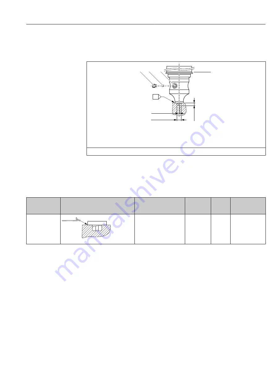
PMP51, version prepared for diaphragm seal mount – welding
recommendation
Version XSJ: prepared for diaphragm seal mount
A1
ø7.95 (0.31)
ø2.5 (0.1)
5 (0.2)
1
2
3
4
A0028495
1
Hole for filling fluid
2
Bearing
3
Setscrew
A1 See the "Welding recommendation" table below
Engineering unit mm (in)
For the version "XSJ - Prepared for diaphragm seal mount" in feature 110 "Process connec-
tion" in the order code up to and including 40 bar (600 psi) sensors, Hauser rec-
ommends welding on the diaphragm seal as follows: the total welding depth of the fillet
weld is 1 mm (0.04 in) with an outer diameter of 16 mm (0.63 in). Welding is performed
according to the WIG method.
Consecutive seam
no.
Sketch/welding groove shape, dimension
as per DIN 8551
Base material matching
Welding
method DIN
EN ISO 24063
Welding
position
Inert gas, additives
A1 for sensors ≤
40 bar (600 psi)
t1 a0.8
A0024811
Adapter made of AISI 316L
(1.4435) to be welded to dia-
phragm seal made of AISI
316L (1.4435 or 1.4404)
141
PB
Inert gas
Ar/H 95/5
Additive:
ER 316L Si (1.4430)
Information on filling
The diaphragm seal must be filled as soon as it has been welded on.
• After welded into the process connection, the sensor assembly must be properly filled
with a filling oil and sealed gas-tight with a sealing ball and lock screw.
Once the diaphragm seal has been filled, at the zero point the device display should not
exceed 10% of the full scale value of the cell measuring range. The internal pressure of
the diaphragm seal must be corrected accordingly.
• Adjustment / calibration:
• The device is operational once it has been fully assembled.
• Perform a reset. The device must then be calibrated to the process measuring range as
described in the Operating Instructions.


