background image

CyBio Carry

Installation and commissioning

25

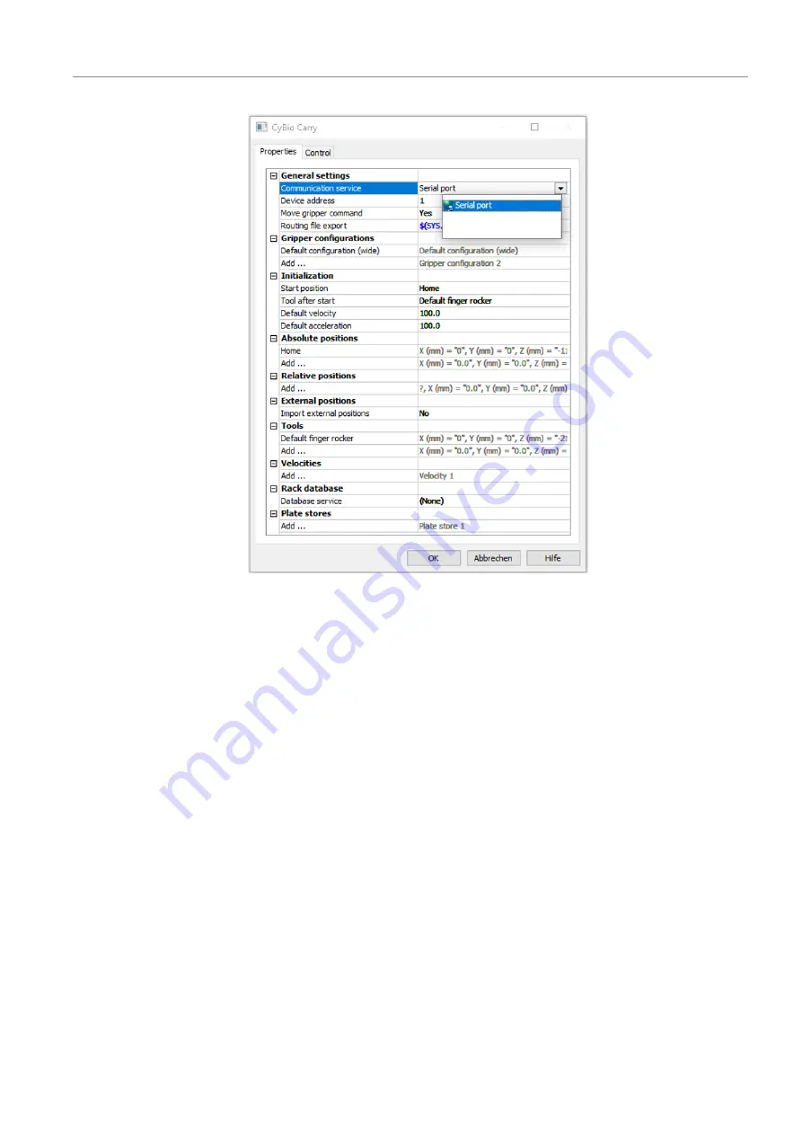
Fig. 19

CyBio Carry window

}

Under 

General settings

|

Communication service

, select the serial interface. 

The tool and the gripper configuration are preset in the software and do not need to
be changed.

}

Optionally: adjust the default speed and acceleration under 

Initialization

(A setting of 50 means that the gripper fingers move at 50% of the preset speed.)

}

Confirm your selection with 

[OK]

.

Summary of Contents for analytikjena CyBio Carry

Page 1: ...Assembly Instructions CyBio Carry...

Page 2: ...se 1 07745 Jena Germany Phone 49 3641 77 9449 Fax 49 3641 77 767776 Email service lha analytik jena com General Information http www analytik jena com Documentation Number 30 3951 1xx 23E Edition A 05...

Page 3: ...uirements 17 3 4 Scope of delivery 18 4 Installation and commissioning 19 4 1 Installation conditions 19 4 1 1 Ambient conditions 19 4 1 2 Spatial requirements 19 4 1 3 Power supply 19 4 2 Commissioni...

Page 4: ...Bio Carry 4 8 1 Transport 42 8 2 Preparing the device for transport 42 8 3 Moving the device in the laboratory 44 8 4 Storage 44 9 Disposal 45 10 Specifications 46 10 1 Technical data 46 11 Maintenanc...

Page 5: ...occurring in chronological order are numbered and combined into action units Warnings are indicated by a warning triangle and a signal word The type source and consequences of the hazard are stated t...

Page 6: ...Y direction and 245 mm in Z direction The device can briefly transport a weight of up to 500 g For proper use please observe the following The device must only be operated by qualified and trained pe...

Page 7: ...bels have been attached to the device and must always be observed Damaged or missing warning and mandatory action labels can cause incorrect actions leading to personal injury or material damage The l...

Page 8: ...uipped with the following protective devices Emergency stop button At the drive box of the linear axis Stops all movement immedi ately Protective glass At the gripper tower Stops all movement immedi a...

Page 9: ...he device Work particularly carefully and cleanly with infectious material because the device cannot be decontaminated as a whole Before using a cleaning or decontamination procedure other than that p...

Page 10: ...cribed in the user manual in the Maintenance and care chapter may be performed by the operator Work on the electronics may only be carried out by the customer service of Analytik Jena and specially au...

Page 11: ...ff 1 Emergency stop button 2 On Off switch 3 Drive box If there is no immediate risk of injury stop the device movement in a dangerous situa tion with the emergency stop button Alternatively switch th...

Page 12: ...s The gripper fingers can be moved in 3 1 axes X Y Z gripper move ment The device can briefly transport a weight of up to 500 g Fig 3 CyBio Carry transports labware The CyBio Carry is intended for int...

Page 13: ...rotective screen 7 LED with status indicator The gripper tower can move along the linear axis in X direction on the guide During operation the rear of the gripper tower is turned towards the user The...

Page 14: ...jaws are attached to the two bottom finger elements The gripper jaws grip the labware on the left and right at its solid edge The gripper jaws have silicone mats on the inside which enables the gripp...

Page 15: ...linear axis Connections and in terfaces 16 In an emergency the user can stop the device immediately with the emergency stop button The maximum speed in X direction is 500 mm s When the gripper finger...

Page 16: ...It is completing a preset sequence Yellow A protective device has stopped the movement Red A device error has occurred Type plates The type plates are attached to the bottom of the gripper tower and t...

Page 17: ...interface for connecting additional lab devices using the same control computer External power supply unit The power supply unit is a wide range power supply unit The voltage supply on the pri mary si...

Page 18: ...the labware in landscape format 3 4 Scope of delivery The following components are included in the delivery CyBio Carry plate transport system consisting of CyBio Carry X linear axis variant CyBio Car...

Page 19: ...isture could damage the sensitive electronics during commissioning Position the device so that the emergency stop button and the on off switch are al ways easily accessible The following requirements...

Page 20: ...tware installation basic installation settings and device configuration Instruction in the operation The device is controlled by means of an external PC and the CyBio Composer software The software co...

Page 21: ...ay Position the plate transport system so that it can easily reach the transfer positions of the devices with extended gripper fingers Maximum deflection in Y direction 290 mm 4 3 Device configuration...

Page 22: ...w services In the Services area click on New The Add a new service window opens Define the following services Interface service Device service Fig 15 Add a new service window Define a new interface se...

Page 23: ...me cy bio_carry to the service Exit the window with OK You have defined a new device configuration with interface and device services The device configuration should look as follows Fig 17 New device...

Page 24: ...the device is connected to the control computer Do not change the other settings Exit the window with OK You have defined the interface to the control computer 4 3 3 Configuring the device and defini...

Page 25: ...vice select the serial interface The tool and the gripper configuration are preset in the software and do not need to be changed Optionally adjust the default speed and acceleration under Initializati...

Page 26: ...posi tion Transfer position where the labware is put down or taken up Define at least one transfer position for each device in the system Set it very precisely as an absolute position in the teach di...

Page 27: ...se an empty microplate Define the parking positions in relation to transfer positions so that you do not have to re teach the parking positions after each change to the system Connect the positions vi...

Page 28: ...ool The entry for Tools Default finger rocker changes from No to Yes Click OK to close the window You have defined a transfer position for transferring labware in the device config uration Defining a...

Page 29: ...e transfer position via a travel path To do so click on the arrow next to Add in the Ways section Select the correct transfer position from the list as the target Fig 24 Selecting the target position...

Page 30: ...o for Y mm The gripper fingers should be completely retracted in the safety position Connect the safety position to the correct parking position and the neighboring safety positions and or the neighbo...

Page 31: ...teach tool or an empty mi croplate Position the teach tool microplate in the nest Click on Pick up 30 3951 540 24 in the Teach tool section to pick up the plate The plate can only be picked up if the...

Page 32: ...27 CyBio Carry Teach Dialog window with warning and prohibition signs After completing the teach dialog click on Put back 30 3951 540 24 to place the plate back in the nest Click on OK to exit the te...

Page 33: ...lights up when the arrow keys are ac tive For safety reasons the device cannot be controlled via the arrow keys during opera tion Fig 28 Control panel with arrow keys and 2 LEDs Move the gripper in t...

Page 34: ...e the device with another software Clicking on Later just minimizes the software message You cannot continue to operate the device without calibration The software cannot start calibration if the grip...

Page 35: ...The drives are in an unknown position Fig 31 Software message Object in shelf Remove the microplate from the shelf Move the gripper upwards with the Arrow up key until you can reach into the shelf Ma...

Page 36: ...ingers fully with the arrow keys Control device with arrow keys 33 Use the Arrow down key to move the gripper over the shelf or a nearby position to reduce the drop height Click on Yes to open the gri...

Page 37: ...e target position automatically Store plate internally Command for getting and putting down microplates in the nest The device finds the way from the current position to the next safety position autom...

Page 38: ...not calibrated The gripper has to be cali brated before a different movement can be executed Restart the method and fol low the on screen instruc tions CyBio Carry reports a device error The device r...

Page 39: ...Motor stall error detected actual and target position do not match Remove the obstacle Repeat the move command Check whether the axes can move freely 167 187 207 227 247 Motor motor electronics over...

Page 40: ...Troubleshooting CyBio Carry 40 Error code Cause Remedy 65535 ESTOP One of the safety devices has trig gered an emergency stop Correct the emergency and then restart the device...

Page 41: ...electrical components and cables for damage Protective conductor test only by a qualified electrician 7 2 Cleaning the device Use a soft cloth dipped in mild soapy or disinfectant solution to clean t...

Page 42: ...he original packaging Empty the device completely and attach all transport locks before transporting the device Add a suitable desiccant to the packaging to prevent damage from moisture Remove all mic...

Page 43: ...the recesses at the edges of the side parts The brackets have a long and a short end and can be installed in only one way The tool required to remove the brackets is screwed to the transport box Unsc...

Page 44: ...rts and disconnect all connections from the device For safety reasons two persons are required to transport the device one person on each side of the device As the device does not have carrying handle...

Page 45: ...CyBio Carry Disposal 45 9 Disposal At the end of its service life the device and its electronic components must be dis posed of as electronic waste in accordance with the applicable regulations...

Page 46: ...5 mm 1775 mm 2375 mm Height 530 mm Depth 140 mm 450 mm with protective glass and maximally extended gripper fingers Weight 19 kg 22 5 kg 24 kg 28 5 kg X axis travel path 800 mm 1200 mm 1400 mm 2000 mm...

Page 47: ...s Weight 8 0 kg Electrical connection Operating voltage 24 V DC max 4 A Power consumption 80 VA Interfaces RS 232 Ethernet External power supply unit data Input voltage 100 to 240 V 10 AC max 1 5 A 50...

Page 48: ...CyBio Carry Y Z gripper tower Component Part number Protective glass 30 3951 520 10 M4 pressure screws 30 101 541 30 101 101 Toothed belts Bando 30 101 780 30 101 783 30 101 324 30 101 712 Grooved bal...

Page 49: ...yBio Carry X linear axis Component Part number Tension spring 30 3951 133 28 Grooved ball bearings 30 102 311 30 016 550 Toothed belt 30 102 164 Toothed belt Bando 30 101 750 Flat flex cables 30 102 1...

Page 50: ...window 22 Fig 16 Add a new service window 23 Fig 17 New device configuration with defined services 23 Fig 18 Properties Serial port window 24 Fig 19 CyBio Carry window 25 Fig 20 Supporting points in t...

Reviews: