EMTRON EIC USER MANUAL
WWW.EMTRON.WORLD
© EMTRON AUSTRALIA PTY LTD APRIL 2018
33
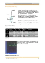
Sensor Supply and Wiring
The sensor is powered through a pullup resistor. The
minimum supply voltage is 8V, ideally a regulated supply
should be used to ensure consistent readings. Figure 6.0
illustrates how the sensor should be wired.
NOTE:
If the pullup resistor is too big there will be
insufficient current to make the output switch. Typical
Pullup resistor range is 330 Ohms to 1000 Ohms.
NOTE:
The Low and High outputs levels will vary with
different sensors, so for signal integrity each sensor output
should be checked using an oscilloscope. Table 6.1 show
some typical results from a Toyota Sensor
Figure 6.0. Sensor Wiring
Supply Pullup
Resistance
Low
Output
High
Output
Switching
Range
Comments
5V
330 Ohms
5.2V
5.2V
0.0V
Insufficient Current
8V
330 Ohms
3.6V
5.9V
2.3V
(see Figure 6.1)
12V
330 Ohms
7.6V
9.9V
2.3V
8V
470 Ohms
5.25V
5.25V
0.0V
Insufficient Current
12V
470 Ohms
6.3V
9.45V
3.15V
Table 6.1
Figure 6.1 shows a scope trace of a MR Sensor with 330R
pullup supplied at 8V. The High Output level is 5.9V and
the Low Output Level is 3.6V.
Figure 6.1. Scope trace of MR Sensor.

