EMTRON EIC USER MANUAL
WWW.EMTRON.WORLD
© EMTRON AUSTRALIA PTY LTD APRIL 2018
16
4.13 EIC Data Monitoring for Single Device
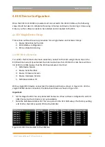
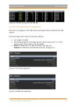
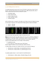
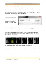
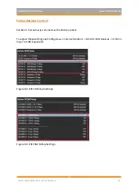
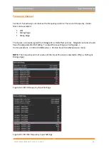
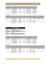
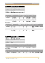
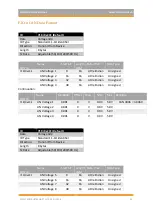
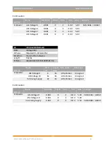
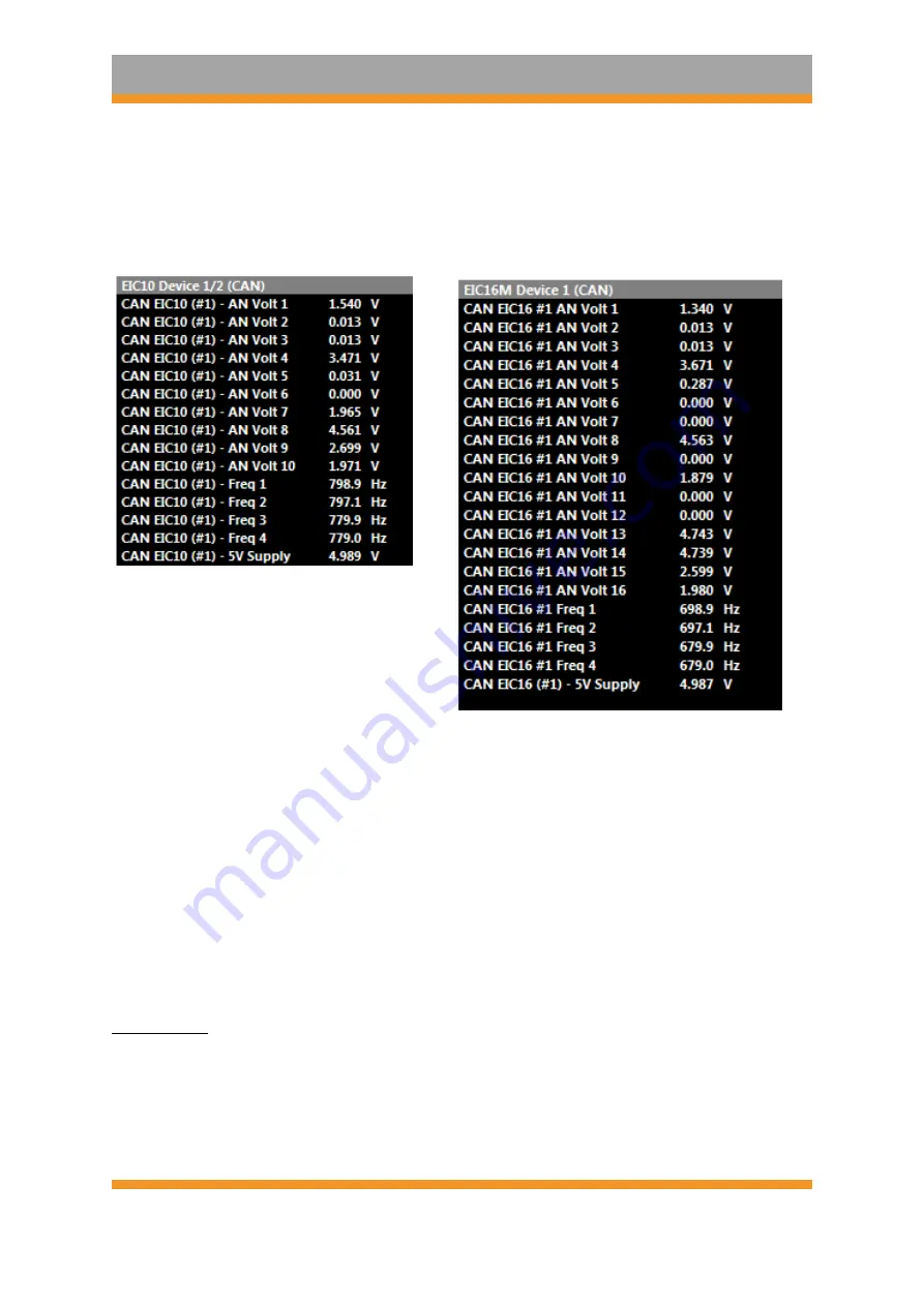
To confirm the EIC data is being decoded by the ECU, open the ECU runtime menu (F3) ->
Emtron CAN Device Tab. The EIC10/EIC16M live data can be viewed. See Figure 4.4 and 4.5.
Figure 4.4. EIC10 CAN Live Data
–
x1 Device
Figure 4.5. EIC16M CAN Live Data
–
x1 Device
4.2 EIC Multiple Device Setup
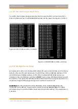
As mentioned in section 3.4, the Base CAN Address ID used to transmit Data over the Bus by
default is the same for each device type. The EIC10 has a factory CAN Base Address of 718
and EIC16M has a CAN Base Address of 705. When multiple EIC10/EIC16M devices are
installed on the same CAN Bus, each device
MUST
have a unique CAN Base Address to avoid
Bus conflicts. This means the CAN Base Address ID will need to be reprogrammed which is a
simple task using the ID Reprogramming Tool as outlined in section 4.22.
REMEMBER:
For this process to function effectively, when multiple
new
devices are
introduced to the CAN bus, they should be initially connected
one at a time.
This allows
each device to sync up to the CAN Bus baud rate and store that setting. This usually takes 3-
5 seconds.

