EMTRON EIC USER MANUAL
WWW.EMTRON.WORLD
© EMTRON AUSTRALIA PTY LTD APRIL 2018
14
4.0 EIC Device Configuration
Once the EIC10 or EIC16M is powered and connected to the ECU’s CAN bus, the following
steps should be taken to complete the setup. All setup and device monitoring is done using
Emtune, so this software needs to be installed and connected to the ECU.
4.1 EIC Single Device Setup
This section outlines the setup procedure for a single device and involves 3 steps:
1.
Device Detection by the ECU
2.
ECU CAN Bus configuration
3.
EIC Live Data Monitoring
4.11 EIC Device Detection
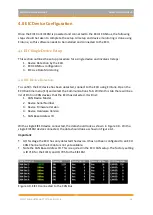
To confirm the EIC device has been detected, connect to the ECU using Emtune. Open the
ECU Runtime menu (F3) and select the Communications Tab. Within this tab there will be a
list of Emtron CAN devices that the ECU has detected. It will list:
1.
CAN Device Model
2.
Device Serial Number
3.
Device Firmware Version
4.
Device Hardware Version
5.
CAN Base Address ID
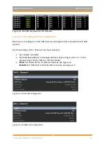
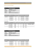
With a single EIC10 device connected, the data should look as shown in Figure 4.0. With a
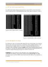
single EIC16M device connected, the data should look as shown in Figure 4.1.
Important
:
▪
At this stage the ECU has only detected the device. It has not been configured to an ECU
CAN Channel so the EIC data is not yet available.
▪
Note the CAN Base Address ID. This is required in the ECU CAN setup. The factory setting
is ID 718 for the EIC10, and ID 705 for the EIC16M
Figure 4.0. EIC10 connected to the CAN Bus

