


12433-10-0109
Page 16
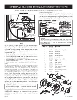
DVB-1 For Direct Vent Wall Furnaces DV-210-(7, 9)SG and DV-215-(7, 9)SG
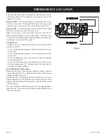
BLOWER
MOUNTING
TAB
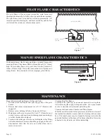
Cleaning the Blower Wheel
In some areas, such as near bedrooms and on floors with a hard surface,
the blower wheel will be filled with lint very quickly. A visual check of
the blower wheel should be made after 30 days use. The blower will run
faster with a dirty wheel, but move less air. Remove the entire blower and
clean each blade of the wheel with a tooth brush as often as necessary.
Figure 1
INSTALLING OPTIONAL BLOWER DVB-1.
The blower must be posi-
tioned as shown in Figure 1. Relocate gas line, if necessary, using elbow
fitting at the gas valve, and move Piezo Spark Generator to the next screw.
A slot on the bottom of the blower package engages a tab on the bottom
of the inner casing and is secured by one screw in front.
Attaching Switch Box
1. Facing combustion chamber, remove (2) top, left screws on the com
-
bustion chamber door.
2. Align (2) clearance holes on the switch box (with fan control) over (2)
clearance holes on the combustion chamber door.
3. Insert and attach (2) screws removed in Step 1 into switch box and
combustion chamber door.
4. Attach switch box cover to switch box with (1) No. 8 x 1/4" screw.
Wiring
The appliance, when installed, must be electrically grounded in accordance
with local codes or, in the absence of local codes, with the National Elec-
trical Code, ANSI/NFPA 70 or Canadian Electrical Code, CSA C22.1, if
an external electrical source is utilized. This appliance is equipped with
a three-prong [grounding] plug for your protection against shock hazard
and should be plugged directly into a properly grounded three-prong re-
ceptacle. Do not cut or remove the grounding prong from this plug. For
an ungrounded receptacle, an adapter, which has two prongs and a wire
for grounding, can be purchased, plugged into the ungrounded receptacle
and its wire connected to the receptacle mounting screw. With this wire
completing the ground, the appliance cord plug can be plugged into the
adapter and be electrically grounded. A 7/8" (22mm) hole is provided in
the junction box for use with a conduit connector if local codes require
this type of protection.
CAUTION: Label all wires prior to disconnection when servicing
controls. Wiring errors can cause improper and dangerous operation.
Verify proper operation after servicing.
Oiling the Motor
Oiling holes are provided on each end of the motor for oiling. The blower
should have five drops of #20 motor oil every 6 months. Do not use
machine oil.
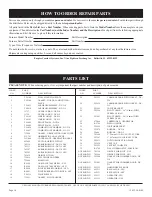
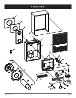
index no.
Part no. Description
1
R-1268
Wire Assembly
2
R-896
Bushing (Three Required)
3
R-1156
Fan Control
4
DV-806
Switch Box
5
DV-807
Switch Box Cover
6
TH-111
junction Box
7
R-1410
Bushing (Strain Relief)
8
R-285
Motor
9
R-587
Motor Cushion
10
TH-341
Blower Cushion
11
TH-356
Motor Support Assembly
12
R-319
Blower Wheel
13
TH-135
Blower Housing Assembly
14
R-315
Cord Set
oPtional BloWer installation instructions
Warning:
Unplugging of blower accessory will not stop the heater from cycling.
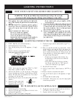
To shut heater off: 1. Turn the temperature dial to lowest setting, then
turn thermostat to off. 2. Turn knob on gas control to off, depressing
slightly. Do not force.


