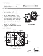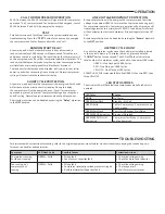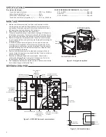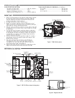
MOUNTING
TROUBLESHOOTING
For assistance with system troubleshooting, refer to the original equipment manufacturer's instructions accompanying the condensing unit,
furnace or air handler, and thermostat.
OPERATION
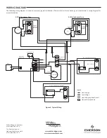
CALL FOR COMPRESSOR OPERATION
24
VAC between the
Y
and
C
terminals will signal a call for compressor
operation. The
C
compressor and fan outputs will be energized. Loss of
24
VAC between
Y
and
C
will de-energize the outputs.
TEST
SureSwitch includes a Test Mode to assist in system installation and
troubleshooting. Press the “
TEST
” button for one second to energize
the compressor and fan for five seconds without a
Y
call.
RANDOM START DELAY
A
t power-up and when SureSwitch recovers from a brownout, a
random start delay of
5-90
seconds will be activated. This delay is in
addition to the short cycle delay. During this delay the compressor will
not be energized, even if a call for compressor operation is present. The
random start delay can help reduce spikes in power consumption when
multiple loads are re-energized after a blackout or brownout.
The random start delay cannot be disabled, but is only active at initial
power-up and when recovering from a brownout. Normal compressor
cycling will not activate the random start delay.
SHORT CYCLE PROTECTION
At power-up, and any time the compressor is de-energized, SureSwitch
will activate a three minute short cycle delay. During this delay
the compressor will not be energized, even if a call for compressor
operation is present, to prevent compressor damage due to rapid on
and off cycling. Normal operation resumes when the delay expires.
Short cycle protection can be disabled by setting the “
Delay
” dipswitch
to the
OFF
position.
LINE-VOLTAGE BROWNOUT PROTECTION
Brownout protection will de-energize the compressor and fan if line
voltage drops below
180
VAC for more than four seconds during a call
for compressor operation. Compressor operation will not resume until
line voltage returns to a minimum of
190
VAC. In addition, SureSwitch
will not attempt to start the compressor if line voltage is less than
187
VAC.
Brownout protection can be disabled by setting the “
Brown
” dipswitch
to the
OFF
position.
LIFETIME CYCLE COUNT
A count of compressor cycles since the control was installed is stored
in the control’s memory. To display the count, press and hold the
“
COUNT
” button for one second. The LED will flash to indicate the
total number of compressor cycles, rounded to the nearest
100
cycles:
GREEN – One Flash per
10,000
Cycles
RED – One Flash per
1,000
Cycles
YELLOW – One Flash per
100
Cycles
EXAMPLE:
52,318
cycles would flash five GREEN, then two RED, then
three YELLOW
LED STATUS CODES
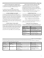
The tri-color LED will flash fault and status codes while
SureSwitch is
powered.
LED Color
Status
NONE
No Power
GREEN Slow Flash
Standby – No Call
GREEN Solid
Call for Compressor – Compressor and
Fan Energized
GREEN Fast Flash
Short Cycle/Random Start Delay
GREEN/RED Alternating
Brownout Detected
GREEN/RED/YELLOW
Alternating
Compressor Test Mode – Compressor
and fan Energized
Symptom
LED Flash Code
Possible Causes
Corrective Actions
Compressor running,
but fan not running
GREEN – Solid
• Wiring fault
• Fan motor or capacitor fault
• Check line voltage wiring
• Check fan motor and capacitor
Fan running, but
compressor not
running
GREEN – Solid
• Wiring fault
• Compressor internal/overload protector tripped
• Run/Start/Hardstart Capacitor Fault
• Check line voltage wiring
• Check capacitors
• Wait for protector to reset
SPECIFICATIONS


