B - 67
Vission 20/20 • Operation and Service Manual •Vilter/Emerson • 35391SC 2.0
Appendix B
•
Vission 20/20 Application Procedures
HARDWARE WIRING
Interconnect wiring between the Vission 20/20 panel
and the VPLUS panel now needs to be done.
1. First make sure that the VPLUS panel and the
Vission 20/20 panel control power comes from the
same source.
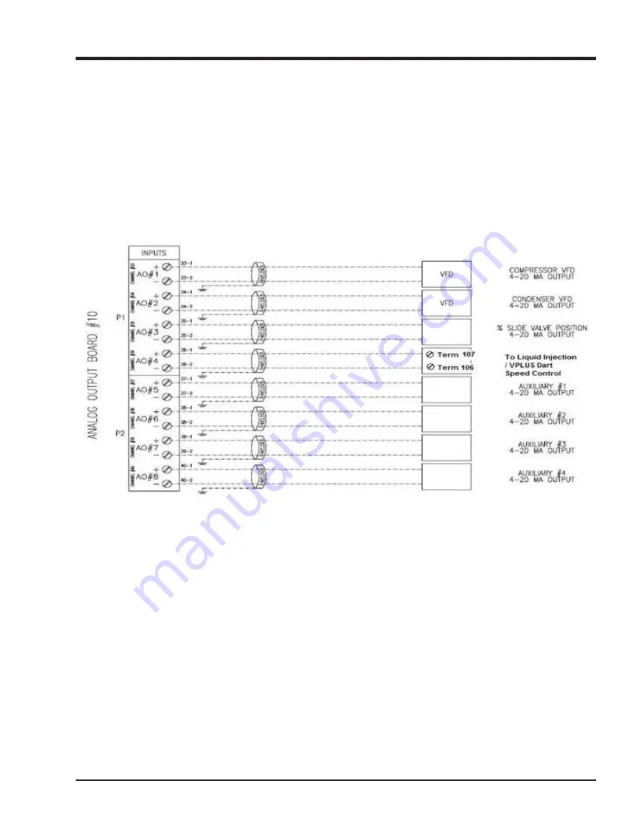
2. Next, the Vission 20/20 analog output card must be
wired to the Dart speed controller board. The ana-
log output that is used for this is AO#4, see Figure
B-43. Wires from AO#4 will land on wires 106 and
107, see Figure B-42.
3. Finally, the VPLUS relay (CRV) shown in Figure B-42
must also be wired to the Vission 20/20. This relay
will be controlled by the Vission 20/20 digital out-
put (board #2, output #5) – the liquid injection so-
lenoid output. Run a wire from terminal 25 in the
20/20 panel to terminal 104 in the VPLUS panel, see
Figure B-43.
Figure B-43. Analog Output Card Wiring to VPLUS Dart Speed Controller (Wire 106 and 107)
Summary of Contents for Vission 20/20
Page 1: ...Vission 20 20 micro controller Operation and service manual Version 2 0 ...
Page 2: ......
Page 4: ......
Page 6: ......
Page 66: ...8 4 Blank Vission 20 20 Operation and Service Manual Vilter Emerson 35391SC 2 0 ...
Page 76: ...10 8 Blank Vission 20 20 Operation and Service Manual Vilter Emerson 35391SC 2 0 ...
Page 86: ...12 6 Blank Vission 20 20 Operation and Service Manual Vilter Emerson 35391SC 2 0 ...
Page 106: ...15 4 Blank Vission 20 20 Operation and Service Manual Vilter Emerson 35391SC 1 9 ...
Page 108: ...16 2 Blank Vission 20 20 Operation and Service Manual Vilter Emerson 35391SC 2 0 ...
Page 136: ...21 4 Blank Vission 20 20 Operation and Service Manual Vilter Emerson 35391SC 2 0 ...
Page 146: ...24 4 Blank Vission 20 20 Operation and Service Manual Vilter Emerson 35391SC 2 0 ...
Page 154: ...26 4 Blank Vission 20 20 Operation and Service Manual Vilter Emerson 35391SC 2 0 ...
Page 156: ...A 2 Blank Vission 20 20 Operation and Service Manual Vilter Emerson 35391SC 2 0 ...
Page 158: ...B 2 Blank Vission 20 20 Operation and Service Manual Vilter Emerson 35391SC 2 0 ...
Page 162: ...B 6 Blank Vission 20 20 Operation and Service Manual Vilter Emerson 35391SC 2 0 ...
Page 180: ...B 24 Blank Vission 20 20 Operation and Service Manual Vilter Emerson 35391SC 2 0 ...
Page 204: ...B 48 Blank Vission 20 20 Operation and Service Manual Vilter Emerson 35391SC 2 0 ...
Page 220: ...B 64 Blank Vission 20 20 Operation and Service Manual Vilter Emerson 35391SC 2 0 ...
Page 257: ......


