


Quick Installation Guide
00825-0100-4750, Rev BB
January 2013
Rosemount 8750WA
10
S
TEP
4: I
NSTALLATION
Flanged Sensors
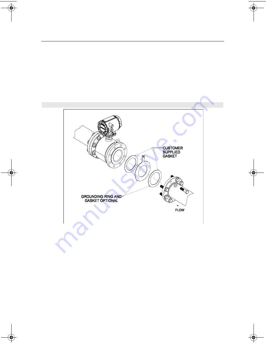
Gaskets
The sensor requires a gasket at each of its connections to adjacent devices or piping. The gasket
material selected must be compatible with the process fluid and operating conditions. Metallic or
spiral-wound gaskets can damage the liner. Gaskets are required on each side of a
grounding ring. All other applications (including sensors with lining protectors or a grounding
electrode) require only one gasket on each end connection.
Flange Bolts
Suggested torque values by sensor line size and liner type are listed in Table 1 on page 11.
Consult the factory if the flange rating of the sensor is not listed. Tighten flange bolts on the
upstream side of the sensor in the incremental sequence shown in Figure 8 on page 11 to
20% of the suggested torque values. Repeat the process on the downstream side of the
sensor. For sensors with more or less flange bolts, tighten the bolts in a similar crosswise
sequence. Repeat this entire tightening sequence at 40%, 60%, 80%, and 100% of the
suggested torque values or until the leak between the process and sensor flanges stop.
If leakage has not stopped at the suggested torque values, the bolts can be tightened in
additional 10% increments until the joint stops leaking, or until the measured torque value
reaches the maximum torque value of the bolts. Practical consideration for the integrity of
the liner often leads the user to distinct torque values to stop leakage due to the unique
combinations of flanges, bolts, gaskets, and sensor liner material.
Check for leaks at the flanges after tightening the bolts. Failure to use the correct tightening
methods can result in severe damage. Sensors require a second tightening 24 hours after
the initial installation. Over time, sensor liner materials may deform under pressure.
Figure 7. Flanged gasket placement
4750RevBBQIG.fm Page 10 Friday, January 11, 2013 6:26 PM