background image

Reference Manual 

00809-0100-4882, Rev AB 

June 2019 


Rosemount 5081FG 

B-2 


Summary of Contents for Rosemount 5081FG

Page 1: ...Reference Manual 00809 0100 4882 Rev AB June 2019 RosemountTM 5081FG Two Wire In Situ Oxygen Analyzer 550 C to 1600 C ...

Page 2: ......

Page 3: ...tallation 2 2 Locating Oxygen Probe 2 2 Installing Oxygen Probe 2 4 Locating Rosemount 5081 Transmitter 2 7 Installing Rosemount 5081 Transmitter 2 8 Electrical Installation 2 11 General 2 11 Oxygen Probe Signal Connections 2 12 Rosemount 5081 Transmitter 4 20 mA and Signal Connections 2 13 Pneumatic Installation 2 14 General 2 14 Reference Air Package 2 14 Instrument Air Reference Air 2 14 Calibr...

Page 4: ...Cal Check Menu 3 21 In Manual 3 21 Accept High O2 3 22 Accept Low O2 3 22 Slope 3 23 Constant 3 23 SECTION 4 HART AMS Overview 4 1 Field Communicator Signal Line Connections 4 2 Field Communicator PC Connections 4 4 Off Line and On Line Operations 4 4 HART AMS Menu Tree 4 4 Field Communicator Start Cal Check Method 4 8 SECTION 5 Troubleshooting General 5 1 Probe Life 5 1 Fault Indications 5 3 Iden...

Page 5: ...100 4882 Rev AB June 2019 Rosemount 5081FG TOC 3 SECTION 7 Replacement Parts APPENDIX A Safety Data Safety Instructions A 2 Safety Data Sheet for Ceramic Fiber Products A 3 APPENDIX B Return of Material Returning Material B 1 ...

Page 6: ...Reference Manual 00809 0100 4882 Rev AB June 2019 Rosemount 5081FG TOC 4 ...

Page 7: ...proper installation operation and maintenance of the product Install your equipment as specified in the Installation Instructions of the appropriate Instruction Manual and per applicable local and national codes Connect all products to the proper electrical and pressure sources To ensure proper performance use qualified personnel to install operate update program and maintain theproduct When repla...

Page 8: ...sconfiguration of end users equipment This could be intentional or unintentional and needs to be protected against Physical security is an important part of any security program and fundamental to protecting your system Restrict physical access by unauthorized personnel to protect end users assets This is true for all systems used within the facility WARNING ...

Page 9: ...S and NOTES found throughout this publication SYMBOLS NOTE Highlights an essential operating procedure condition or statement EARTH GROUND TERMINAL PROTECTIVE CONDUCT OR TERMINAL RISK OF ELECTRICAL SHOCK WARNING REFER TO INSTRUCTIONMANUAL NOTE TO USERS The number in the lower right corner of each illustration in this publication is a manual illustration number It is not a part number and is not re...

Page 10: ...ne For assistance with technical problems please call the North American Response Center The Response Center is staffed 24 hours a day 7 days a week Phone 1 800 654 RSMT 1 800 654 7768 Emerson may also be reached via the Internet through email and the World Wide Web Email GAS CSC emerson com ...

Page 11: ...gure 1 1 Record the part number serial number and order number for each component of your system in the table located on the first page of this manual Also use the product matrix in Table 1 1 at the end of this section to compare your order number against your unit The first part of the matrix defines the model The last part defines the various options and features of the Rosemount 5081FG Analyzer...

Page 12: ... 1 1 Typical System Package 1 Instruction Manual 2 Rosemount 5081 Transmitter 3 Oxygen Probe 4 Adapter Plate with Mounting Hardware and Gasket Optional 5 Infrared Remote Control IRC 6 Reference Air Set Optional 7 Field Communicator Package Optional 8 Pipe Mounting Kit Optional ...

Page 13: ...loped across a heated electrochemical cell which consists of a small yttria stabilized zirconia disc Both sides of the disc are coated with porous metal electrodes When operated at the proper temperature the millivolt output voltage of the cell is given by the following Nernst equation EMF KT log10 P1 P2 C Where 1 P2 is the partial pressure of the oxygen in the measured gas onone side of the cell ...

Page 14: ...olated output 4 20 mA that is proportional to the measured oxygen concentration A customer supplied 24 VDC power source is required to simultaneously pro vide power to the electronics and a 4 20 mA signal loop The transmitter accepts millivolt signals generated by the probe and produces the outputs to be used by other remotely connected devices The output is an isolated 4 20 mA linearized current ...

Page 15: ...on DD software specific to the Two Wire In Situ Oxygen Analyzer The DD software will be supplied with many field communicators but can also be programmed into existing units at most Fisher Rosemount service offices See Section4 HART AMS for additional HARTinformation Personal Computer PC The use of a personalcomputer requires AMS software available fromFisher Rosemount 9 Selected Distributed Contr...

Page 16: ... the components select mounting locations and determine how each component will be placed in terms of available line voltage ambient temperatures environmental considerations convenience and serviceability Figure 1 1 shows a typical system package A typical system installation is shown in Figure 1 3 Figure 1 3 Typical System Installation It is important that printed circuit boards and integrated c...

Page 17: ...se any components are to be shipped to another site This packaging has been designed to protect the product SPECIFICATIONS Transmitter Net O2 Range 0 to 25 O2 System Accuracy 1 5 of reading or 0 05 O2 whichever is greater System Response in Flue Gas Initial less than 3 seconds T90 less than 8 seconds Probe Lengths 20 in 508 mm 26 in 660 mm 38 in 965 mm Process Temperature Limits 550 to 1400 C 1022...

Page 18: ... sealed Power Supply and Load Requirements See Figure 1 4 Inputs from O2 Probe Two wires O2 signal Two wires type B thermocouple Output One 4 20 mA signal with superimposed digital HART signal Hazardous Area Certification See Section 8 Power Transient Protection IEC 801 4 Hazardous Area Certification ATEX EEx ia IIC Class 1 Div 1 Group A B C D Figure 1 4 Power Supply and Load Requirements Shipping...

Page 19: ...de Mounting Adapter ProbeSide 0 No adapter plate 1 ANSI 2 in 150 lb flange to 1 25 NPTadapter 6 in dia flange 4 75 in BC with 4 x 0 75 in dia holes 2 DIN to 1 25 NPT adapter 184 mm flange 145 mm BC with 4 x 18 mm dia holes 3 JIS to 1 25 NPT adapter 155 mm flange 130 mm BC with 4 x 13 mm dia holes 4 Model 450 to 1 25 NPT adapter 5 Competitor s mounting flange Code Electronics Housing TYPE 4X IP65 H...

Page 20: ...Reference Manual 00809 0100 4882 Rev AB May 2019 Rosemount 5081FG 1 10 ...

Page 21: ...ge 2 2 Mechanical Installation page 2 2 Electrical Installation page 2 11 Pneumatic Installation page 2 14 Before installing this equipment read the Safety instructions for the wiring and installation of this apparatus in Appendix A Failure to follow safety instructions could result in serious injury or death ...

Page 22: ...of a bend may not provide a representative sample because of the very low flow conditions The sensing point should be selected so the process gas temperature falls within a range of 550 to 1400 C 1022 to 2552 F Figure 2 1 provides mechanical installation references 2 Check the flue or stack for holes and air leakage The presence ofthis condition will substantially affect the accuracy of the oxygen...

Page 23: ...Reference Manual 00809 0100 4882 Rev AB May 2019 Rosemount 5081FG 2 3 Figure 2 1 Probe Installation Details ...

Page 24: ...re 2 5 Use pipe couplings and nipples to adjust the probe insertiondepth 5 Use high temperature material alumina wool to seal around the probe during insertion This prevents hot gases from escaping or cold air from entering the stack or duct 6 Initially insert the probe to a depth of 3 in 76 2 mm or 1 2 the depth of the stack or duct refractory whichever is greater 7 After initial insertion insert...

Page 25: ...Reference Manual 00809 0100 4882 Rev AB May 2019 Rosemount 5081FG 2 5 Figure 2 2 Optional Adapter Plate Figure 2 3 Optional Probe Mounting Flange ...

Page 26: ...Reference Manual 00809 0100 4882 Rev AB May 2019 Rosemount 5081FG 2 6 Figure 2 4 Horizontal Probe Installation ...

Page 27: ...ion Depth Locating Rosemount 5081 Transmitter 1 Ensure the Rosemount 5081 transmitter is easily accessible for maintenance and service and for using the infrared remote control if applicable Do not allow the temperature of the Rosemount 5081 transmitter exceed 65 C 149 F or damage to the unit may result ...

Page 28: ...7 m ofthe oxygen probe due to wiring and signalconsiderations 1 Ensure all components are available to install the Rosemount5081 transmitter 2 Choose a method or location to mount thetransmitter a Flat Surface Mounting The transmitter may be mounted on a flat surface using the threaded mounting holes located on the bottomof the transmitter housing Refer to Figure 2 6 for installation references b ...

Page 29: ...Reference Manual 00809 0100 4882 Rev AB May 2019 Rosemount 5081FG 2 9 Figure 2 7 Pipe Mounting Dimensions ...

Page 30: ...ock is disengaged from the knurled surface on the threaded circuit end cap b Remove the circuit end cap c Remove the three screws retaining the display board inplace d Lift and rotate the display board 90 degrees eitherway e Reposition the display board on the standoffs Install and tightenall three screws f Install the circuit end cap and tighten the cover lock screw tosecure the cover lock in pla...

Page 31: ...y from other electrical equipment and 6 5 ft 2 m from heavy electrical equipment For intrinsically safe applications refer to the installation drawings on Emerson com for the model 5081FG Disconnect and lock out power before connecting the unit to the power supply Install all protective equipment covers and safety ground leads after installation Failure to install covers and ground leads could res...

Page 32: ...l connections on the transmitter housing to prevent moisture accumulation in the terminal side of the housing 1 Two signals represent the O2 value and the cell temperature The probe provides these values to the Rosemount 5081 transmitter for processing and signal conditioning 2 Wiring connections for the probe are shown in Figure2 9 Figure 2 9 Oxygen Probe Terminal Block Moisture accumulation in t...

Page 33: ...field communicator or AMS software 2 Two signals representing the O2 value and the cell temperature are supplied to the Rosemount 5081 transmitter from the oxygen probe 3 Wiring connections for the Rosemount 5081 transmitter are shown in Figure 2 10 NOTE The ground arrangement shown in Figure 2 10 limits the amount of noise introduced into the electronics 4 Connect wire shields to terminal 1 Conne...

Page 34: ...er the oxygen probe is installed connect the reference air set Installthe reference air set according to Figure 2 11 Instrument Air Reference Air Instrument air is required for reference Refer to the reference air schematic Figure 2 12 Use 10 psig 68 95 kPa gage minimum 225 psig 1551 38 kPa gage at 0 2 scfh 100 m min less than 40 parts per million total hydrocarbons Regulator outlet pressure shoul...

Page 35: ...2 13 Gas Connections at Oxygen Probe Do not use 100 nitrogen for the low 0 check gas See Figure 2 13 for the probe connections Set both calibration check gases at the same flow rate 5 scfh 2 5 min Do not use 100 nitrogen as a low gas zero gas It is suggested that gas for the low zero be between 0 4 and 2 0 O2 Do not use gases with hydrocarbon concentrations of more than 40 parts per million Failur...

Page 36: ...Reference Manual 00809 0100 4882 Rev AB May 2019 Rosemount 5081FG 2 16 ...

Page 37: ... UP General The Two Wire In Situ Oxygen Analyzer displays the current oxygen reading on the LCD face of the Rosemount 5081 transmitter The O2 concentration cell temperature and 4 20 mA output current are displayed as shown in Figure 3 1 This and other information may also be accessed using HART AMS Startup Display When the probe is first inserted into the stack some time is required until the mini...

Page 38: ... After the probe has reached operating temperatures the Rosemount 5081 transmitter display should look similar to Figure 3 1 The display will now track the O2 concentration cell temperature and 4 20 mA output current Figure 3 1 Normal Operation Display Figure 3 2 Faulted Operation Display ...

Page 39: ...heck gas flow rate at startup It is not necessary to perform this procedure for each calibration check 1 Adjust the calibration check gas flow to 5 scfh 2 5 min to ensure the cell is surrounded by calibration check gas Due to the cooling effect of the gas the cell temperature will decrease slightly causing the O2 concentration to drop Once the electronics compensates for this effect the O2 concent...

Page 40: ...er to Section 4 HART AMS Display The LCD on the circuit end of the Rosemount 5081 transmitterdisplays O2 concentration cell temperature and 4 20 mA output current during normal operation Figure 3 4 The LCD will also display fault conditions when they occur To interact with the transmitter use the IRC and navigate through a series of menus displayed on the LCD Menu Tree The screens that can be disp...

Page 41: ...Reference Manual 00809 0100 4882 Rev AB May 2019 Rosemount 5081FG 3 5 Figure 3 5 Transmitter Menu Tree ...

Page 42: ...to avoid undesired or repeated commands from accumulating in the command queue 2 Use the keys on the IRC to navigate through the menu screens Refer to Figure 3 6 General usage is as follows a RESET Returns to the PROCESS DISPLAY screen at the top of the menu tree Any non entered number in the exited state will be ignored and the previous data will be used b HOLD Not used c Left Right Arrow Moves l...

Page 43: ...is branch is accessed sequentially using the NEXT key Refer to Figure 3 5 during the following menu and screen descriptions NOTE To edit a screen value press ENTER to access the data field Use the left and right arrow keys to move among the digits in the data field Note that the editable position will be flashing To change the value of a digit use the up and down arrow keys to increase or decrease...

Page 44: ...At this point you can either specify the analyzer by its access code or view its code if it is unknown 1 To gain further access to the screens in the PROGRAM MENU branch enter the correct three digit analyzer access code using the arrowkeys and press ENTER If security is disabled this screen does not appear and the system displays the FAULT VALscreen 2 If the analyzer access code is un known enter...

Page 45: ...scribed in Code To return to the CODE screen press NEXT Fault Val Refer to Figure 3 9 Use this screen to set the value that the 4 20mA output will drive to and display during a fault condition Press ENTER to begin editing Use the arrow keys to enter a fault value The fault value can be between 3 8 and 24 mA Then press ENTER to accept the value Pressing NEXT displays the UPPER RANGE VAL screen Refe...

Page 46: ...nge value can be between 0 and 25 Then press ENTER to accept the value Pressing NEXT displays the CELL T HIscreen Cell T Hi Refer to Figure 3 11 Use this screen to set the value of the upper cell temperature fault condition This value is the maximum allowed cell temperature before a fault condition is indicated Press ENTER to begin editing Use the arrow keys to select and change the value The valu...

Page 47: ... the value Pressing NEXT displays the SET O2 FILTER TIME screen Set O2 Filter Time Refer to Figure 3 13 In some applications it is beneficial to dampen theraw O2 signal coming from the cell Use this screen to enter the amount of time it will take the O2 to reach 90 of the new reading Press ENTER to begin editing Use the arrow keys to select and change the screen value to the O2 filter value in sec...

Page 48: ...081 transmitter terminals 15 and 16 power up the unit and return to the TRIM 4 mA screen Press ENTER to begin editing Use the arrow keys to select and change the screen value to the value displayed on the installed ammeter Press ENTER to accept the value After the value is entered the unit calibrates itself to ensure it outputs 4 mA Both the display and the ammeter will display 4 mA Pressing EXIT ...

Page 49: ... transmitter terminals 15 and 16 power up the unit and return to the TRIM 20 mAscreen Figure 3 15 Trim 20mA Press ENTER to begin editing Use the arrow keys to select and change the screen value to the value displayed on the installed ammeter Press ENTER to accept the value After the value is entered the unit calibrates itself to ensure it outputs 20 mA Both the display and the ammeter will display...

Page 50: ...the O2 percentage of the high calibration check gas Press ENTER to accept the value Set Lo Bottle O2 Refer to Figure 3 17 Use this screen to identify within the electronics the percentage of O2 used as the low calibration check gas Press ENTER to begin editing Use the arrow keys to select and change the screen value to the O2 percentage of the low calibration check gas Press ENTER to accept the va...

Page 51: ...e O2 value steady during the calibration check Press ENTER to accept the value Press NEXT to display the SET CODE screen Set Code Refer to Figure 3 19 Use this screen to set the security codefor the Rosemount 5081 transmitter Press ENTER to begin editing Use the arrow keys to select and change the value Select any value between 000 and 999 excluding 000 and 555 Code 000 indicates that no code is s...

Page 52: ...Y screen Normal or Faulted Each screen in this branch is accessed sequentially by pressing NEXT Refer to the menu in Figure 3 5 when reviewing the following menu and screens Show Fault Refer to Figure 3 20 After pressing DIAG this screendisplays Pressing ENTER accesses a screen displaying the current fault if any If morethan one fault exists and you are in the FAULT screen press NEXT to go to the ...

Page 53: ...Reference Manual 00809 0100 4882 Rev AB May 2019 Rosemount 5081FG 3 17 Figure 3 20 Show Fault ...

Page 54: ...this screen to examine the cellthermocouple mV output Three decimal places are displayed Pressing NEXT accesses the O2 CELL mV screen O2 CELL mV Refer to Figure 3 22 Use this screen to examine the O2 CELL mV output Pressing NEXT accesses the CELL IMPEDANCE screen Figure 3 21 T C mV Figure 3 22 O2 CELL mV ...

Page 55: ...perature influences cell impedance Wait until the cell is at operating temperature before checking cell impedance If checked before the cell reaches 550 C 1022 F this screen displays a fail indication Current Slope Refer to Figure 3 24 Use this screen to examine the slope calculatedfrom the most recent calibration check The slope is the amount of cell voltage generated for a given O2 value For eac...

Page 56: ...e reference and process sides of the cell Press NEXT to access the PREVIOUS SLOPE screen Previous Slope Refer to Figure 3 26 Use this screen to examine the slope value stored from the second to last calibration check The slope is the amount of cell voltage generated for a given O2 value For each calibration check record the slope over the life of the probe Tracking the slope will indicate if the p...

Page 57: ...esents the voltage generated by the cell when no difference exists between the amount of O2 on the reference and process sides of the cell Press NEXT to access the MAX CELL T screen Max Cell T Refer to Figure 3 28 Use this screen to examine themaximum temperature attained by the O2 cell This value can be reset under the PROGRAM MENU Pressing NEXT accesses the SW VER screen Figure 3 27 Previous Con...

Page 58: ... calibration check ensure the high calibration check gas and low calibration check gas O2 percentages are entered into the electronics via the PROGRAM MENU To set these values refer to Set Hi Bottle O2 and Set Lo Bottle O2 Once these values are set access the CAL CHECK MENU branch by pressing CAL on the IRC when in the PROCESS DISPLAY screen Normal or Faulted Each screen in this branch identifies ...

Page 59: ... O2 value to settle press NEXT to accept the high calibration check gas reading and apply the low calibration check gas The next screen to display is the ACCEPT LOW O2 screen Accept Low O2 Refer to Figure 3 31 Once the low calibration check gas is applied wait approximately three minutes for the displayed O2 value to settle Once the value settles press NEXT to accept the reading and to display the...

Page 60: ...e slope will indicate if the probe is degrading Press NEXT to access the CONSTANT screen Constant Refer to Figure 3 33 Use this screen to examine the cellzero constant calculated from the current calibration check The constant represents the voltage generated by the cell when no difference exists between the amount of O2 on the reference and process sides of the cell Note this value for comparison...

Page 61: ...ific functions of the keypad keys To interface with the Rosemount 5081FG Analyzer the field communicator requires a termination point along the 4 20 mA current loop and a minimum load resistance of 250 ohms between the field communicator and the power supply The field communicator accomplishes its task using a frequency shift keying FSK technique With the use of FSK high frequency digital communic...

Page 62: ...nal line load resistance is less than 250 ohms refer to method 2 Method 1 For Load Resistance 250 Ohms Refer to Figure 4 1 and the following steps to connect the field communicator to a signal line 250 ohms or more of load resistance Using the supplied lead set connect the field communicator in parallel with to the Rosemount 5081FG Analyzer Use any wiring termination points in the analog output 4 ...

Page 63: ...ce 1 At a convenient point break the analog output 4 20 mA signal line and install the optional 250 ohm load resistor 2 Plug the load resistor into the rear panel of the field communicator Figure 4 2 Signal Line Connections 250 Ohms Load Resistance Explosions can result in death or serious injury Do not make connections to the field communicator s serial port 4 20 mA signal line or NiCad recharger...

Page 64: ...ected to the 4 20 mA analog output signal line The communicator is connected in parallel to the Rosemount 5081FG Analyzer or in parallel to the 250 ohm load resistor NOTE If the field communicator is turned on while connected to the 4 20 mA analog output signal line an undefined status indication appears while the communicator warms up Wait until the warm up period ends to continue The opening men...

Page 65: ...Reference Manual 00809 0100 4882 Rev AB May 2019 Rosemount 5081FG 4 5 Figure 4 3 HART AMS Menu Tree Sheet 1 of 3 ...

Page 66: ...Reference Manual 00809 0100 4882 Rev AB May 2019 Rosemount 5081FG 4 6 Figure 4 3 HART AMS Menu Tree Sheet 2 of 3 ...

Page 67: ...Reference Manual 00809 0100 4882 Rev AB May 2019 Rosemount 5081FG 4 7 Figure 4 3 HART AMS Menu Tree Sheet 3 of 3 ...

Page 68: ...en a Loop should be removed from automaticcontrol warning appears Remove the analyzer from any automatic control loops to avoid undesirable equipment performance and pressOK 6 The next screen prompts you to apply the high calibration check gas This message will only display for approximately three seconds Press OK 7 At this point calibration check gas will flow for approximately three min utes unt...

Page 69: ...evels of SO2 and low levels of O2 are particularly damaging The health and accuracy of a given cell is closely related to the resistance or impedance of the cell Figure 5 1 illustrates that the amount of output from a cell for a given O2 value represented as slope will remain very stable to the point where cell impedance increases to approximately 100 ohms Frequently conduct calibration checks to ...

Page 70: ...Reference Manual 00809 0100 4882 Rev AB May 2019 Rosemount 5081FG 5 2 Figure 5 1 Slope vs Impedance Figure 5 2 Speed of Response ...

Page 71: ...re In Situ Oxygen Analyzer will be indi cated by the faulted operation display as shown in Figure 5 3 This screen displays when a fault that invalidates the O2 reading is present When the error is corrected the screen will return to a normal operation display unless another error exists Figure 5 3 Faulted Operation Display ...

Page 72: ...tion The following paragraphs describe the faults possible causes and corrective actions Refer to Figure 5 4 as needed for test points and wiring information NOTE Allow adequate time for the oxygen probe to reach its operating temperature approximately 500 C 932 F before investigating a fault The SHOW FAULTS screen of the DIAGNOSTICS menu will indicate a fault until the unit reaches operating temp...

Page 73: ... probe per Oxygen Probe Replacement in Section 6 Maintenance and Service Figure 5 6 Fault 2 Reversed Thermocouple Fault 2 Reversed ThermocoupleActive The thermocouple connections are reversed The fault displays as shown in Figure 5 6 1 Allow adequate time for the oxygen probe to reach operating temperatures Probe temperatures below approximately 500 C 932 F may result in this fault 2 Refer to Figu...

Page 74: ...orted 4 If the thermocouple is shorted replace the oxygen probe per Oxygen Probe Replacement in Section 6 Maintenance and Service 5 If the thermocouple is not shorted then replace the faulty analog or CPU board per Electronics Replacement in Section 6 Maintenance and Service Figure 5 8 Fault 4 High Probe Temperature Fault 4 High ProbeTemperature The probe s temperature has exceeded the maximum cel...

Page 75: ...tion check gas 0 4 O2 Measure the cell output from the O2cell wires at the probe terminal block The cell output should be 100 20 mV If no voltage can be measured the cell is open 4 If the O2 cell is open replace the oxygen probe per Oxygen Probe Replacement in Section 6 Maintenance and Service Figure 5 10 Fault 6 Cell Impedance Too High Fault 6 Cell Impedance Too High The O2 cell impedance has exc...

Page 76: ...rd per Electronics Replacement in Section 6 Maintenance and Service CALIBRATION PASSES BUT STILL READS INCORRECTLY Probe Passes Calibration O2 Still Reads High There are fault conditions where no alarm indication is present and the probe passes calibration but the O2 reading may still be incorrect External Reference Air Leak There may be a leak that is permitting ambient air to mix with the proces...

Page 77: ...d surface of circuit end cap 14 Remove circuit endcap 2 Remove three screws 13 retaining the electronics inplace 3 Lift display board 12 to disconnect from CPU board 11 The display board is plugged into the CPU board use care when removing the display board 4 Align and plug the replacement display board 12 in the desired orientation Carefully plug the display board into the mating connector on CPU...

Page 78: ...Reference Manual 00809 0100 4882 Rev AB May 2019 Rosemount 5081FG 6 2 Figure 6 1 Two Wire In Situ Oxygen Analyzer Exploded View ...

Page 79: ...e earlier model analyzer uses a ribbon cable to connect the display board 12 to the CPU board 10 7 Install new spare board stack into housing 1 Carefully seat the analog board onto housing pins Press firmly on the CPU board standoffs to ensure good contact 8 Align and plug the replacement display board 12 into the mating connector on the CPU board 11 Ensure the display board is fully seated 9 Inst...

Page 80: ...hanical installation instructions 6 Refer to Electrical Installation in Section 2 Installation for electrical installation instructions 7 Refer to Pneumatic Installation in Section 2 Installation for reference air and calibration check gas installationinstructions Use heat resistant gloves and clothing when removing the probe The probe can be as hot as 1600 C 2912 F This can cause severe burns Do ...

Page 81: ...Reference Manual 00809 0100 4882 Rev AB May 2019 Rosemount 5081FG 6 5 Figure 6 2 Oxygen Probe Terminal Block ...

Page 82: ...Reference Manual 00809 0100 4882 Rev AB May 2019 Rosemount 5081FG 6 6 ...

Page 83: ... 6A00093G03 Rosemount 5081 Transmitter FM 1 1 3 5R10092G01 20 Replacement Oxygen Probe with Alumina Outer Protection Tube 1 1 3 5R10092G02 26 Replacement Oxygen Probe with Alumina Outer Protection Tube 1 1 3 5R10092G03 38 Replacement Oxygen Probe with Alumina Outer Protection Tube 1 1 3 5R10092G09 20 Replacement Oxygen Probe with Inconel 600 Outer Protection Tube 1 1 3 5R10092G10 26 Replacement Ox...

Page 84: ...clearly defined in the respective codes USA FM Certificate FM17US0021X Standards FM Class 3600 2011 FM Class 3610 2015 FM Class 3611 2016 FM Class 3615 2006 FM Class 3810 2005 ANSI TYPE 250 1991 Markings Intrinsically Safe for use in Class I II and III Division 1 Groups A B C D E F and G T4 Ta 20 C to 70 C Per Control Drawing Numbers 1400227 1400228 Nonincendive for Class I Division 2 Groups A B C...

Page 85: ...equipment enclosure may contain light metals The equipment must be installed in such a manner as to minimize the risk of impact or friction with other metal surfaces International IECEx Certificate IECEx BAS 09 0159X Standards IEC 60079 0 2011 IEC 60079 11 2011 Markings Ex ia IIC T4 Ga 20 Ta 65 C Special Conditions for Safe Use X 1 The Model 5081 enclosure may be made of aluminum alloy and given a...

Page 86: ...Reference Manual 00809 0100 4882 Rev AB May 2019 Rosemount 5081FG Appendix A Safety Data Safety Instructions page A 1 Safety Data Sheet for Ceramic Fiber Products page A 2 ...

Page 87: ... a mechanically operated isolating switch If not then another means of disconnecting the equipmentfrom the supply must be provided and clearly marked as such Circuit breakers or switches must comply with a recognized standard such as IEC947 All wiring must conform with any localstandards 7 Where equipment or covers are marked with the symbol to the right hazardous voltages are likely to be present...

Page 88: ...lvania Drive Columbia MO 65202 573 814 1300 ext 5170 573 474 9402 HEALTH HAZARD SUMMARY WARNING Possible cancer hazard based on tests with laboratory animals May be irritating to skin eyes and respiratorytract May be harmful if inhaled Cristobalite crystalline silica formed at high temperatures above 1800ºF can cause severe respiratorydisease SECTION II PHYSICAL DATA APPEARANCE AND ODOR Cream to w...

Page 89: ...N HAZARDS SPECIAL FIRE FIGHTING PROCEDURES N A SECTION V HEALTH HAZARD DATA THRESHOLD LIMIT VALUE See Section III EFFECTS OF OVER EXPOSURE EYE Avoid contact with eyes Slightly to moderatelyirritating Abrasive action may cause damage to outer surface ofeye INHALATION May cause respiratory tract irritation Repeated or prolonged breathing of particles of respirable size may cause inflammation of the ...

Page 90: ...ase in some measures of pulmonary function These observations are clinically insignificant In other words if these observations were made on an individual employee the results would be interpreted as being within the normal range 4 Pleural plaques thickening along the chest wall have been observed in a small number of employees who had a long duration of employment There are several occupational a...

Page 91: ...ficulties administer oxygen until medical assistance can be rendered INGESTION Do not induce vomiting Get medical attention if irritation persists SKIN CONTACT Do not rub or scratch exposed skin Wash area of contact thoroughly with soap and water Using a skin cream or lotion after washing may be helpful Get medical attention if irritation persists SECTION VI REACTIVITY DATA STABILITY CONDITIONS TO...

Page 92: ...oggles to prevent eye contact Do not wear contact lenses when working with this substance Have eye baths readily available where eye contact can occur SECTION IX SPECIAL PRECAUTIONS PRECAUTIONS TO BE TAKEN IN HANDLING AND STORING General cleanliness should be followed The Toxicology data indicate that ceramic fiber should be handled with caution The handling practices described in this MSDS must b...

Page 93: ...e air purifying respirator with high efficiency particulate air HEPA filter cartridges e g 3M 7800S with 7255 filters or equivalent or powered air purifying respirator PARR equipped with HEPA filter cartridges e g 3M W3265S with W3267 filters or equivalent Full face positive pressure supplied air respirator e g 3M 7800S with W9435 hose W3196 low pressure regulator kit connected to clean air supply...

Page 94: ...Reference Manual 00809 0100 4882 Rev AB May 2019 Rosemount 5081FG A 8 ...

Page 95: ...ng the 1 800 654 RSMT 7768 toll free number This center available 24 hours a day will assist you with any needed information or materials The center will ask for product model and serial numbers and will provide a Return Material Authorization RMA number The center will also ask for the process material to which the product was last exposed Emerson Instrument and Valves Response Center representat...

Page 96: ...Reference Manual 00809 0100 4882 Rev AB June 2019 Rosemount 5081FG B 2 ...

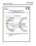
Page 97: ...Reference Manual 00809 0100 4882 Rev AB June 2019 Rosemount 5081FG EC Declaration of Conformity ...

Page 98: ...Reference Manual 00809 0100 4882 Rev AB June 2019 Rosemount 5081FG B 2 ...

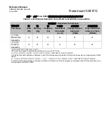
Page 99: ...lectronics Assembly X O O O O O 壳体组件 Housing Assembly X O O X O O 本表格系依据 SJ T11364 的规定而制作 This table is proposed in accordance with the provision of SJ T11364 O 意为该部件的所有均质材料中该有害物质的含量均低于 GB T 26572 所规定的限量要求 O Indicate that said hazardous substance in all of the homogeneous materials for this part is below the limit requirement of GB T 26572 X 意为在该部件所使用的所有均质材料里 至少有一类均质材料中该有害物质的含量高于 GB T 26572 所规定的限量...

Page 100: ......

Page 101: ...ploded View 6 2 F Fault 1 Open Thermocouple 5 5 Fault 2 Reversed Thermocouple Active 5 5 Fault 3 Shorted Thermocouple 5 6 Fault 4 High Probe Temperature 5 6 Fault 5 O2 Cell Open 5 7 Fault 6 Cell Impedance Too High 5 7 Fault 7 Reversed O2 Cell 5 8 Fault Indications 5 3 Faulted Operation Display 5 3 Field Communicator PC Connections 4 4 H Handling the Analyzer 1 6 HART AMS Menu Tree 4 4 Horizontal P...

Page 102: ...d Stack Replacement 6 3 Specifications 1 7 Start Cal Check Method HART 4 8 Symbols iv System Configuration 1 4 System Considerations 1 6 System Description 1 3 System Features 1 4 System Overview 1 3 T Technical Support Hotline iv Transmitter 4 20 mA and Signal Connections 2 13 Transmitter Mounting Dimensions Flat Surface 2 8 Pipe 2 9 Transmitter Terminal Block 5 4 Troubleshooting 5 1 Typical Syst...

Page 103: ...Index 2 ...

Page 104: ...in tort including negligence Rosemount does not warrant equipment against normal deterioration due to environment Factors such as corrosive gases and solid particulates can be detrimental and can create the need for repair or replacement as part of normal wear and tear during the warranty period Equipment supplied by Rosemount but not manufactured by it will be subject to the same warranty as is e...

Page 105: ...ope GmbH Neuhofstrasse 19a P O Box 1046 CH 6340 Baar Switzerland 1 954 846 5030 1 952846 5121 Gas CSC Emerson com Asia Pacific Emerson Automation Solutions Asia Pacific Pte LTD 1 Pandan Crescent Singapore 128461 65 6777 8211 65 6777 0947 Gas CSC Emerson com Middle East Emerson Automation Solutions Emerson FZE P O Box 17033 Jebel Ali Free Zone South 2 971 4 8118100 971 4 88665465 Gas CSC Emerson co...

Reviews: