Reference Manual
00809-0100-4882, Rev AB
May 2019
Rosemount 5081FG
4-2
FIELD COMMUNICATOR
SIGNAL LINE
CONNECTIONS
The field communicator can connect to the analyzer's analog output signal
line at any wiring termination in the 4-20 mA current loop. There are two meth-
ods of connecting the field communicator to the signal line. For applications in
which the signal line has a load resistance of 250 ohms or more, refer to
method 1. For applications in which the signal line load resistance is less than
250 ohms, refer to method 2.
Method 1, For Load Resistance
250 Ohms
Refer to Figure 4-1 and the following steps to connect the field communicator
to a signal line < 250 ohms or more of load resistance.
Using the supplied lead set, connect the field communicator in parallel with to
the Rosemount 5081FG Analyzer. Use any wiring termination points in the
analog output 4-20 mA signal line.
Figure 4-1. Signal Line Connections,
250 Ohms Load Resistance
Explosions can result in death or serious injury. Do not make connections to the field
communicator's serial port, 4-20 mV signal line, or NiCad recharger jack in an explosive
atmosphere.
Summary of Contents for Rosemount 5081FG
Page 2: ......
Page 6: ...Reference Manual 00809 0100 4882 Rev AB June 2019 Rosemount 5081FG TOC 4 ...
Page 20: ...Reference Manual 00809 0100 4882 Rev AB May 2019 Rosemount 5081FG 1 10 ...
Page 36: ...Reference Manual 00809 0100 4882 Rev AB May 2019 Rosemount 5081FG 2 16 ...
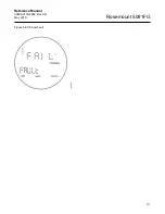
Page 53: ...Reference Manual 00809 0100 4882 Rev AB May 2019 Rosemount 5081FG 3 17 Figure 3 20 Show Fault ...
Page 82: ...Reference Manual 00809 0100 4882 Rev AB May 2019 Rosemount 5081FG 6 6 ...
Page 94: ...Reference Manual 00809 0100 4882 Rev AB May 2019 Rosemount 5081FG A 8 ...
Page 96: ...Reference Manual 00809 0100 4882 Rev AB June 2019 Rosemount 5081FG B 2 ...
Page 98: ...Reference Manual 00809 0100 4882 Rev AB June 2019 Rosemount 5081FG B 2 ...
Page 100: ......
Page 103: ...Index 2 ...


