background image

121

Product Certifications

Product Certifications

July 2017

Reference Manual 

00809-0100-2230, Rev CA

B.12  Conduit plugs and adapters

IECEx Flameproof and Increased Safety

Certificate: IECEx FMG 13.0032X

Standards: IEC60079-0:2011, 

IEC60079-1:2007-04, 
IEC60079-7:2006-07

Markings: Ex de IIC Gb

ATEX Flameproof and Increased Safety

Certificate: FM13ATEX0076X

Standards: EN60079-0:2012, 

EN60079-1:2007, 
IEC60079-7:2007

Markings: 

 II 2 G Ex de IIC Gb

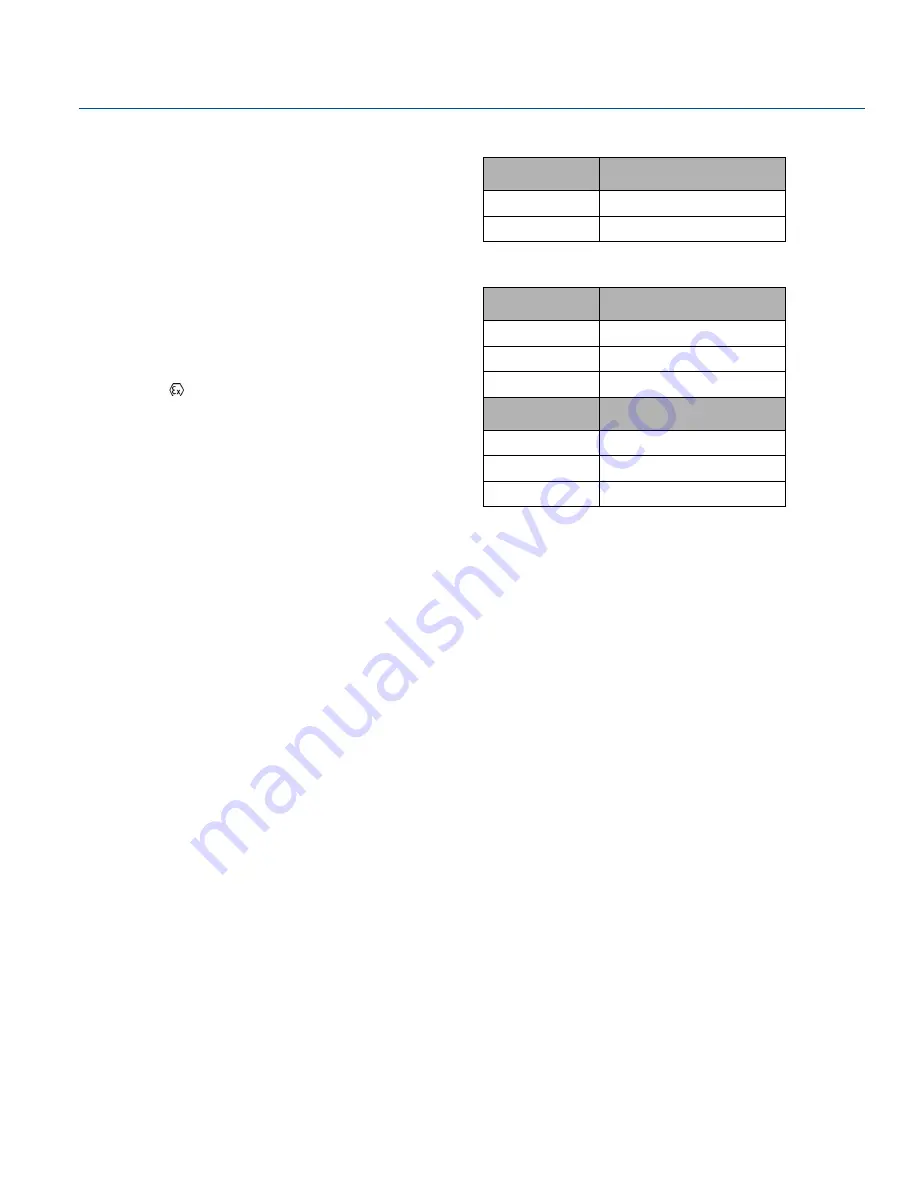
B.12.1  Conduit Plug Thread Sizes

B.12.2  Thread Adapter Thread Sizes

Special Conditions for Safe Use (X):

1. When the thread adapter or blanking plug is used with an 

enclosure in type of protection increased safety “e” the entry 
thread shall be suitably sealed in order to maintain the 
ingress protection rating (IP) of the enclosure.See certificate 
for special conditions.

2. The blanking plug shall not be used with an adapter.

3. Blanking Plug and Threaded Adapter shall be either NPT or 

Metric thread forms. G½ thread forms are only acceptable 
for existing (legacy) equipment installations.

Thread

Identification Mark

M20 x 1.5

M20

½ - 14 NPT

½ NPT

Male Thread

Identification Mark

M20 x 1.5 – 6g

M20

½ - 14 NPT

½ - 14 NPT

¾ - 14 NPT

¾ - 14 NPT

Female Thread

Identification Mark

M20 x 1.5 – 6H

M20

½ - 14 NPT

½ - 14 NPT

G1/2

G1/2

Summary of Contents for Rosemount 2230

Page 1: ...Reference Manual 00809 0100 2230 Rev CA July 2017 Rosemount 2230 Graphical Field Display ...

Page 2: ......

Page 3: ... Any substitution of non recognized spare parts may jeopardize safety Repair e g substitution of components etc may also jeopardize safety and is under no circumstances allowed Rosemount Tank Radar AB will not take any responsibility for faults accidents etc caused by non recognized spare parts or any repair which is not made by Rosemount Tank Radar AB WARNING Substitution of components may impair...

Page 4: ...ii Reference Manual 00809 0100 2230 Rev CA Title Page July 2017 Title Page ...

Page 5: ... 9 2 3 1 System start up 16 2 4 Installation procedure 17 3Section 3 Installation 3 1 Safety messages 19 3 2 Installation considerations 20 3 3 Mechanical installation 21 3 3 1 Mounting the graphical display 21 3 4 Electrical installation 23 3 4 1 Cable conduit entries 23 3 4 2 Grounding 23 3 4 3 Cable selection 24 3 4 4 Hazardous areas 24 3 4 5 Power requirements 25 3 4 6 The Tankbus 25 3 4 7 Typ...

Page 6: ...4 6 2 Select tanks 47 4 6 3 Units for display 48 4 6 4 Toggle time 50 4 6 5 Language 50 4 7 The Service menu 51 4 7 1 Status 52 4 7 2 Custody transfer view 52 4 7 3 LCD test 53 4 7 4 LCD contrast 53 4 7 5 Restart 54 4 7 6 Factory settings 54 4 7 7 About 55 4 8 FOUNDATION Fieldbus overview 56 4 8 1 Block operation 56 4 9 Device capabilities 57 4 9 1 Link Active Scheduler 57 4 9 2 Device addressing ...

Page 7: ... 4 15 1Alert default settings 80 5Section 5 Service and Troubleshooting 5 1 Safety messages 81 5 2 Service 82 5 2 1 Status information 82 5 2 2 Viewing input and holding registers 83 5 2 3 Restarting the Rosemount 2230 display 85 5 2 4 Device error signals 86 5 3 Troubleshooting 88 5 3 1 General 88 5 3 2 Tankbus system 90 5 3 3 Foundation Fieldbus system 92 5 3 4 Device errors 93 5 3 5 Device warn...

Page 8: ...otection 107 5 9 Device Information 109 AAppendix A Specifications and Reference Data A 1 General 111 A 1 1 Toggle time 111 A 1 2 Language selection possibilities 111 A 1 3 Variables to display 111 A 1 4 Units to display 111 A 1 5 View Options 111 A 2 Electric 111 A 2 1 Power supply 111 A 2 2 Tankbus current draw 111 A 2 3 Display type 111 A 2 4 Start up time 111 A 2 5 Update rate 111 A 2 6 Respon...

Page 9: ...ution time 112 A 3 10Instantiation 112 A 3 11Conforming Foundation fieldbus 112 A 3 12Field Diagnostics support NAMUR 107 112 A 3 13Action support wizards 112 A 3 14Advanced diagnostics 112 A 4 Mechanical 112 A 4 1 Housing material 112 A 4 2 Dimensions width x height x depth 112 A 4 3 Weight 112 A 5 Environment 113 A 5 1 Ambient temperature 113 A 5 2 Storage temperature 113 A 5 3 Humidity 113 A 5 ...

Page 10: ...l 120 B 8 Technical Regulations Customs Union EAC 120 B 9 Japan 120 B 10Republic of Korea 120 B 11Additional Certifications 120 B 12Conduit plugs and adapters 121 B 12 1Conduit Plug Thread Sizes 121 B 12 2Thread Adapter Thread Sizes 121 CAppendix C FOUNDATION Fieldbus Block Information C 1 Resource block 123 C 2 Register transducer block 128 C 3 Main transducer block 130 C 3 1 Diagnostic device al...

Page 11: ...s specified in this manual Failure to do so may impair the protection provided by the equipment Explosions could result in death or serious injury Verify that the operating environment of the transmitter is consistent with the appropriate hazardous locations certifications Before connecting a hand held communicator in an explosive atmosphere make sure the instruments in the loop are installed in a...

Page 12: ...n Certificate is a statement of a Notified Certification Body declaring that this product meets the Essential Health and Safety Requirements of the ATEX directive The FM APPROVED Mark indicates that the equipment is approved by FM Approvals according to applicable Approval Standards and is applicable for installation in hazardous locations Protective Earth Ground External cabling must be approved ...

Page 13: ...and electrical installation Section 4 Configuration and Operation describes how to configure the Rosemount 2230 by using the soft key functions or other tools such as a Rosemount 475 Field Communicator or the AMS Device Manager software Section 5 Service and Troubleshooting covers tools troubleshooting and various service instructions Appendix A Specifications and Reference Data contains specifica...

Page 14: ...er WinOpi 303028EN Product data sheets Rosemount Tank Gauging System Data Sheet 00813 0100 5100 Rosemount 2460 System Hub Product Data Sheet 00813 0100 2460 Rosemount 2410 Product Data Sheet 00813 0100 2410 Rosemount 5900S Product Data Sheet 00813 0100 5900 Rosemount 5900C Product Data Sheet 00813 0100 5901 Rosemount 2240S Product Data Sheet 00813 0100 2240 Rosemount 2230 Product Data Sheet 00813 ...

Page 15: ... you can contribute to take care of the environment 1 6 1 Reuse and recycling Experience has shown that wooden boxes can be used several times for various purposes After careful disassembly the wooden parts may be reused Metal waste may be converted 1 6 2 Energy recovery Products which have served their time may be divided into wood and metal components and the wood can be used as fuel in sufficie...

Page 16: ...6 Reference Manual 00809 0100 2230 Rev CA Introduction July 2017 Introduction ...

Page 17: ...ch tank individually The four softkeys at the front of the Rosemount 2230 allow you to navigate through the different menus and provides all tank data directly in the field Data from a group of tanks is buffered by a Rosemount 2460 System Hub and is distributed to a TankMaster PC or a host system whenever the Rosemount 2460 receives a request for data In case no 2460 is included in the system the ...

Page 18: ...otection lid 1 1 It is recommended that the lid is closed whenever possible to protect the LCD from exposure by ultraviolet radiation from the sun B Display C Menu D Soft keys E Activity indicator F Cover screw x6 G Cable entries two 14 NPT optional adapters for two M20 x 1 5 H Ground screw I Clip for locking the weather protection G F A B D H C E I ...

Page 19: ...ransmitters for complete inventory control Such systems are easily expanded thanks to the modular design The Rosemount Tank Gauging system is a versatile system that is compatible with and can emulate all major tank gauging systems Moreover the well proven emulation capability enables step by step modernization of a tank farm from level gauges to control room solutions It is possible to replace ol...

Page 20: ...Bus Modem Rosemount 2460 System Hub Rosemount TankMaster PC Plant Host Computer Rosemount 644 Plant Host Computer NON HAZARDOUS AREA HAZARDOUS AREA Rosemount 2410 Tank Hub Rosemount 5900S Radar Level Gauge Tankbus Segment coupler CUSTODY TRANSFER INVENTORY TANK GAUGING OPERATIONAL CONTROL Rosemount 644 Temperature Transmitter Rosemount 2410 Tank Hub Rosemount 2410 Tank Hub Rosemount 2240S Temperat...

Page 21: ...ankbus Segment coupler Emerson Wireless 775 THUM Adapter Rosemount 5900S Radar Level Gauge Rosemount 2240S Temperature Transmitter Rosemount 2230 Graphical Field Display Rosemount 3051S Pressure Transmitter Rosemount 2410 Tank Hub Rosemount 2410 Tank Hub Rosemount 5900S Radar Level Gauge Rosemount TankMaster PC Rosemount 644 Temperature Transmitter Rosemount 644 Rosemount 644 Emerson Wireless 775 ...

Page 22: ...er FOUNDATION Fieldbus Power Supply CUSTODY TRANSFER INVENTORY TANK GAUGING OPERATIONAL CONTROL Rosemount 644 PC Rosemount 5900S Radar Level Gauge Rosemount 2240S Temperature Transmitter Rosemount 3051S Pressure Transmitter Rosemount 5900S Radar Level Gauge Rosemount 644 Temperature Transmitter Rosemount 5300 Level Transmitter Rosemount 5400 Rosemount 2240S Rosemount 644 Rosemount 644 Rosemount 22...

Page 23: ... temperature transmitters in a buffer memory Whenever a request for data is received the system hub can immediately send data from the updated buffer memory for a group of tanks Measured and calculated data from one or more tanks is communicated via the Rosemount 2410 Tank Hub to the system hub buffer memory Whenever a request is received the system hub can immediately send data from a group of ta...

Page 24: ...evel inside a tank Different antennas can be used in order to meet the requirements of different applications The Rosemount 5900S can measure the level of almost any product including bitumen crude oil refined products aggressive chemicals LPG and LNG The Rosemount 5900S sends microwaves towards the surface of the product in the tank The level is calculated based on the echo from the surface No pa...

Page 25: ...ount 3051S Pressure Transmitter near the bottom of the tank as a complement to a Rosemount 5900S Radar Level Gauge the density of the product can be calculated and presented One or more pressure transmitters with different scalings can be used on the same tank to measure vapor and liquid pressure Rosemount 2180 Field Bus Modem The Rosemount 2180 Field Bus Modem FBM is used for connecting a TankMas...

Page 26: ...cted via a Rosemount 2180 Field Bus Modem or directly via RS 232 or RS 485 5 Install the TankMaster software in the control room PC 6 Configure the devices by using the TankMaster WinSetup configuration tool as described in the Rosemount Tank Gauging System Configuration Manual Document no 00809 0300 5100 FOUNDATION fieldbus To start up Rosemount Tank Gauging devices in a FOUNDATION fieldbus syste...

Page 27: ...ount 2230 Graphical Field Display 1 Review installation considerations Installation considerations on page 20 4 Power up the Rosemount 2230 5 Configure the Rosemount 2230 Section 4 Configuration and Operation 2 Mount the Rosemount 2230 in a suitable location Mechanical installation on page 21 3 Wire the Rosemount 2230 Electrical installation on page 23 ...

Page 28: ...18 Reference Manual 00809 0100 2230 Rev CA Overview July 2017 Overview ...

Page 29: ...s manual Failure to do so may impair the protection provided by the equipment Do not perform any service other than those contained in this manual unless you are qualified Substitution of components may impair Intrinsic Safety To prevent ignition of flammable or combustible atmospheres disconnect power before servicing Explosions could result in death or serious injury Verify that the operating en...

Page 30: ...ay Mount the Rosemount 2230 in a location where it is protected from excessive sunlight This will reduce exposure to ultra violet UV radiation and extend the life time of the LCD In case the LCD can not be protected from sunlight and UV radiation it is recommended that the weather protection lid see Rosemount 2230 components on page 8 is closed whenever the Rosemount 2230 is not used An external w...

Page 31: ...30 Graphical Field Display can be mounted on a wall by using the mounting kit supplied by Emerson Automation Solutions Rosemount Tank Gauging 1 Mount the bracket on the wall by using four M8 screws and flat washers Note Countersunk screws are not suitable 2 Attach the Rosemount 2230 display to the bracket on the wall by sliding it from the top downwards 3 Secure the display to the bracket by tight...

Page 32: ...olutions Rose mount Tank Gauging 1 Attach the bracket to the pipe 2 Ensure that the Rosemount 2230 is placed in a direction so that the display is clearly visible and wiring can be properly connected 3 Tighten the nuts Use moderate torque to ensure that the bracket does not break 4 Attach the display to the bracket by sliding it from the top downwards 5 Secure the display to the bracket by tighten...

Page 33: ...ealant of type PTFE tape shall be used to prevent dust and water ingress and to enable future removal of the plug gland 3 4 2 Grounding The housing should always be grounded in accordance with national and local electrical codes Failure to do so may impair the protection provided by the equipment The most effective grounding method is direct connection to earth ground with minimal impedance There ...

Page 34: ...The cables must be approved for use in hazardous areas where applicable In the U S explosion proof conduits may be used in the vicinity of the vessel We recommend cable size 0 75 mm2 18 AWG in order to facilitate wiring Cables within the range 22 AWG to 16 AWG 0 5 t o1 5 mm can be used in order to minimize the voltage drop to the Rosemount 2230 display Tankbus cabling must be approved for use in m...

Page 35: ...egment the built in termination is enabled at factory Other devices such as the Rosemount 5900S Radar Level Gauge the Rosemount 2230 Graphical Field Display and the Rosemount 2240S Multi input Temperature Transmitter also have built in terminators which can easily be enabled by inserting a jumper in the terminal block when necessary Segment design When designing a FISCO fieldbus segment a few requ...

Page 36: ...ected to the Tankbus and the quality of cables See chapter Electrical Installation in the Rosemount 2410 Reference Manual for more information about cable selection power budget and the tankbus See also Typical Installations in the Rosemount 2410 Reference Manual for more examples of how to install Rosemount Tank Gauging systems that include the Rosemount 2410 Tank Hub Built in terminator Tankbus ...

Page 37: ...Entity parameters of the power supply Ensure that the short circuit protection of the Segment Coupler 2 matches the current consumption of the connected devices Figure 3 5 Example of a Non I S FOUNDATION fieldbus system 1 See Appendix B Product Certifications for Rosemount 2230 approval information 2 See the Rosemount 2410 Reference Manual Document No 00809 0100 2410 for more information on the Se...

Page 38: ...6 on page 29 Ensure that the positive lead is connected to the terminal marked FB and the negative lead to the terminal marked FB 5 Connect the cable shield to the Shield Loop Through X1 terminal 6 If the Rosemount 2230 display is the last device on the Tankbus connect a jumper for the built in termination See The Tankbus on page 25 for more information on termination 7 Replace the cover Make sure...

Page 39: ...able connections A Front cover B X4 Tankbus terminator Sealing C Cable Shield D Internal grounding E Jumper for built in termination F X4 Tankbus terminator X2 Tankbus FB input X3 Tankbus FB input Daisy chain connection to other field devices see page 30 FB FB E F C D B A X2 Tankbus output X3 Tankbus output ...

Page 40: ...is connected to the Tankbus 3 Run the new Tankbus cable into the Rosemount 2230 compartment through a suitable gland 4 Connect the outgoing Tankbus wires to the X2 out and X3 out terminals as shown in Figure 3 7 5 Connect the cable shield to the X1 terminal 6 Replace the cover Make sure the sealing and the locking device for the weather protection hatch are placed in the correct positions 7 Firmly...

Page 41: ...nce is continuously repeated for more information see Device error signals on page 86 Communication LED s Tankbus communication is indicated by a pair of LED s see Figure 3 9 When you connect the Tankbus cables you can check the communication status with the LED s Reset button You may use the Reset button to force a restart of the Rosemount 2230 display Restarting the Rosemount 2230 has the same e...

Page 42: ...de the switch setting Simulate switch The Simulate switch is used for simulation of Field Diagnostics conditions It may be useful when testing the alarm setup Write protect switch The Write Protect switch can be used to protect the Rosemount 2230 from unintentional changes of the current configuration See also Write protection on page 107 Number Name Description 1 Simulate Enables simulation for t...

Page 43: ...e The temperature can be displayed on the field display and in the TankMaster software Ambient temperature affects the readability and response time of the LCD This is particularly notable in extremely cold weather The Rosemount 2230 automatically adjusts the LCD contrast based on the ambient temperature The temperature sensor also controls the minimum toggle time used by the Rosemount 2230 ...

Page 44: ...34 Reference Manual 00809 0100 2230 Rev CA Installation July 2017 Installation ...

Page 45: ... issues is indicated by a warning symbol Please refer to the following safety messages before performing an operation preceded by this symbol Failure to follow safe installation and servicing guidelines could result in death or serious injury Make sure only qualified personnel perform the installation Use the equipment only as specified in this manual Failure to do so may impair the protection pro...

Page 46: ...ich kind of system it is connected to Figure 4 1 The Rosemount 2230 display The four softkeys allow you to navigate through the different menus and to select various functions for tank data viewing and service Menu opens the Main Menu with various options for configuration of the Rosemount 2230 display Pause stops toggling the measurement variables until the Resume button is pressed Down arrow let...

Page 47: ...erent tools are available for configuration of a Rosemount 2230 In systems with Rosemount 2410 Tank Hub Rosemount TankMaster Winsetup In FOUNDATION fieldbus systems Rosemount 475 Field Communicator AMS Device Manager for FOUNDATION Fieldbus systems FOUNDATION Fieldbus hosts supporting DD4 TankMaster is an Emerson Automation Solutions Rosemount Tank Gauging inventory management software package for...

Page 48: ...t 2230 display shows an alarm warning symbol for simulated or manual measurement values as illustrated in Figure 4 2 and Figure 4 3 Figure 4 2 Simulated or manual value For invalid measurement data the alarm symbol is displayed and no data appears in the measurement value field as illustrated in Figure 4 3 Figure 4 3 Invalid value Alarm symbol Invalid value ...

Page 49: ...y 2017 Configuration and Operation The activity indicator spins continuously to indicate that the Rosemount 2230 is operating normally In case of a communication problem an alarm symbol is displayed instead Figure 4 4 Activity indicator Communication problems Normal operation ...

Page 50: ...e Rosemount 2230 display performs a test of the LCD screen when powered on Figure 4 5 Test screen After the LCD test is done the start up screen will appear Figure 4 6 Start up screen Once the start up procedure is finished the Rosemount 2230 will return to the view that was used last time the display was powered on Figure 4 7 View Mode ...

Page 51: ...0809 0100 2230 Rev CA Configuration and Operation July 2017 Configuration and Operation 4 3 Menu tree The Rosemount 2230 lets you navigate in a menu structure as illustrated in Figure 4 8 Figure 4 8 Rosemount 2230 Menu Tree ...

Page 52: ... the Menu softkey on the left hand side Figure 4 10 Main Menu The Main Menu includes the following options Select View which lets you select the preferred view see section Select View menu on page 43 Options which lets you select variables and tanks to display as well as measurement units toggle time and language See section The Options menu on page 44 Service which includes the functions Status C...

Page 53: ...figure the Select View menu 1 In View Mode press the Menu button to navigate to the Main menu 2 Highlight the Select View menu item using the and softkeys 3 Press the softkey 4 In the Select View Menu use the up and down arrow softkeys to navigate to the desired option 5 Press the OK softkey to select the desired option Then the Rosemount 2230 returns to View Mode For example using the Two Values ...

Page 54: ... To choose an item in the Options menu 1 In View Mode press the Menu button to open the Main menu 2 Highlight the Options menu item by using the and softkeys 3 Press the softkey In Foundation fieldbus systems some options are not available This is indicated as illustrated below 4 In the Options Menu use the up and down arrow softkeys to navigate to the desired menu item 5 Press the softkey to cont...

Page 55: ...t of variables to be used for all tanks connected to the same 2410 Tank Hub In addition to this you can configure tanks individually by specifying a unique set of variables for each tank Note that the individual configuration will be added to the configuration that is common for all tanks For a list of selectable variables see Table 4 1 on page 46 To select variables 1 In View Mode press Menu Opti...

Page 56: ...s connected to the tank Vapor Pressure Measured vapor pressure Liquid Pressure Measured liquid pressure Air Pressure Measured air pressure in the tank Ambient Temperature Air temperature outside the tank Vapor Temperature Temperature of vapor inside the tank Liquid Average Temperature Averagte temperature of the product in the tank Tank Temperature Average temperature of the product and vapor in t...

Page 57: ... Pos 1 10 menu lets you select which tanks to present in View Mode Up to ten tanks can be displayed Note that the tanks need to be configured in the tank database of the Rosemount 2410 Tank Hub 2 To select tanks 1 In View Mode press Menu Options Tanks 2 Use the up and down arrow softkeys to navigate to the Tank Pos 1 10 menu item 3 Press the OK softkey to continue to the list of tanks 4 Use the up...

Page 58: ...9 To change measurement unit 1 In View Mode press Menu Options Units for Display 2 Use the up and down arrow softkeys to navigate to the desired variable menu item In the example above the Length variable was chosen 3 Press the softkey to continue to the list of options for the selected variable 4 Use the up and down arrow softkeys to navigate to the desired measurement unit 5 Press the OK softkey...

Page 59: ...units are available for Level rate Meter second Meter hour Feet second Feet hour Flow rate The following units are available for Flow rate Cubic meter hour Barrel hour US gallon hour UK gallon hour Liter minute Volume The following units are available for Volume Cubic meter Barrel US gallon UK gallon Liter Temperature The following units are available for Temperature Degrees Celsius Degrees Fahren...

Page 60: ...the display To set the Toggle Time 1 From View Mode press Menu Options Toggle Time 2 Use the up and down arrow softkeys to increase or decrease the Toggle Time 3 Press the OK softkey to select the desired value and return to View Mode 4 6 5 Language To set the display Language 1 Use the up and down arrow softkeys and navigate to the preferred language option 2 Press the OK softkey to select the la...

Page 61: ...fer View 1 LCD Test LCD Contrast Restart Factory Settings 1 About To choose a Service menu item 1 In View Mode press the Menu button to open the Main menu 2 Use the and softkeys to navigate to the Service option 3 Press the softkey 4 Use the up and down arrow softkeys to navigate to the desired menu item 5 Press the softkey to continue to the selected menu 1 Not available in Foundation fieldbus sy...

Page 62: ... the current status information 1 In the View Mode press Menu Service Status 2 Press Esc to return to the Service menu See Status information on page 82 for information on various status messages 4 7 2 Custody transfer view The Custody Transfer view presents Level and Liquid Temperature for each tank To open the Custody Transfer view 1 In View Mode press Menu Service Custody Transfer 2 Press the E...

Page 63: ...l View Mode 4 7 4 LCD contrast To adjust the LCD contrast 1 In View Mode press Menu Service LCD Contrast 2 Use the up and down arrow softkeys to increase or decrease the LCD contrast 3 Press the OK softkey to select the desired value and return to View Mode In case the contrast is so low that the LCD cannot be properly read it can be adjusted by pressing the appropriate buttons to increase the con...

Page 64: ...oftware and hardware In a Rosemount Tank Gauging system it will connect the Rosemount 2230 to the Rosemount 2410 Tank Hub 4 7 6 Factory settings To restore the Rosemount 2230 to factory settings 1 In View Mode press Menu Service 2 Choose the Factory Settings option and press the softkey 3 Press the OK softkey to restore the Rosemount 2230 to factory settings or press the Esc softkey to cancel 4 Al...

Page 65: ...ion and Operation 4 7 7 About To view the About information 1 In View Mode press Menu Service 2 Choose the About option and press the softkey 3 The About option will present the current software version and the Rosemount 2230 serial number 4 Press the Esc softkey to return to the Service menu ...

Page 66: ...Resource blocks contain the hardware specific characteristics associated with a device they have no input or output parameters The algorithm within a resource block monitors and controls the general operation of the physical device hardware There is only one resource block defined for a device Transducer blocks connect function blocks to local input output functions They read sensor hardware and w...

Page 67: ... fieldbus devices The Link Active Scheduler device LAS device probes a list of addresses to allow devices to come online during normal operation The LAS can skip probing certain addresses in the range to speed up how long it takes to detect new devices on the bus 4 9 3 Capabilities Virtual Communication Relationship VCRs Table 4 4 VCR s Address range decimal Address range hexadecimal Allocation 0 ...

Page 68: ... be helpful to understand the following modes AUTO The functions performed by the block will execute If the block has any outputs these will continue to update This is typically the normal operating mode Out of Service OOS The functions performed by the block will not execute If the block has any outputs these will typically not update and the status of any values passed to downstream blocks will ...

Page 69: ...he MAO blocks A MAO Block is used for receiving measurement data from devices such as the Rosemount 5900S Radar Level Gauge The Rosemount 2230 is supplied with four pre configured MAO blocks according to Table 4 5 on page 59 Each MAO block has eight inputs Note that the CHANNEL parameter value has to be equal to 1 auto in order to provide data output from the MAO block An example of a setup with a...

Page 70: ...r and a Rosemount 5900S Radar Level Gauge Product Level is output from the Rosemount 5900S via an Analog Input block to the Multiple Analog Output Block 1 FFMAO1 in the Rosemount 2230 display as well as to the Analog Output Block FFAO_RMT7 in the Rosemount 2240S Temperature Transmitter for Average Product Temperature calculations Water Level and Average Product Temperature is output from the Rosem...

Page 71: ...for configuration of function blocks that are available for the Rosemount 2230 The Control Studio diagram in Figure 4 11 shows which tank variables that are connected to the Multiple Analog Output blocks in this example MAO Block 1 and MAO Block 2 are configured by using AMS Device Manager as shown in this example MAO Block 1 is configured for Level Liquid Temperature and Free Water Level MAO Bloc...

Page 72: ...hen it clears so that there is no masking of active conditions SOFT W LOCK and HARD W LOCK Inputs to the security and write lock functions include the hardware security switch the hardware and software write lock bits of the FEATURE_SEL parameter and the WRITE_LOCK parameter The WRITE_LOCK parameter prevents modification of parameters within the device except to clear the WRITE_LOCK parameter Duri...

Page 73: ...o zero then no alerts are reported FEATURE_SEL HARDW_LOCK bit FEATURE_SEL SOFTW_LOCK bit SECURITY SWITCH WRITE_LOCK WRITE_LOCK Read Write Write access to blocks 0 off 0 off NA 1 unlocked Read only All 0 off 1 on NA 1 unlocked Read Write All 0 off 1 on NA 2 locked Read Write Function Blocks Only 0 off 1 on NA 2 locked Read Write None 1 on 0 off 1 1 The hardware and software write lock select bits a...

Page 74: ...ps conditions to be detected as active for this alarm category Thus the same condition may be active in all some or none of the four alarm categories The parameter contains a list of conditions in the device which makes the device non operational that will cause an alert to be sent Below is a list of the conditions with the highest priority first This priority is not the same as the FD_FAIL_PRI pa...

Page 75: ... described below It is hard coded within the device and is not user configurable Below is a list of the conditions 1 Invalid Model Code 2 Internal Temperature Out of Limits 3 MAO Fault State Mode Enabled FD_OFFSPEC_MASK The FD_OFFSPEC_MASK parameter will mask any of the failed conditions listed in FD_OFFSPEC_MAP A bit on means that the condition is masked out from alarming and being broadcast to t...

Page 76: ...arameter described below It is hard coded within the device and is not user configurable Note that maintenance alarms are not enabled by default for the Rosemount 2230 FD_MAINT_MASK The FD_MAINT_MASK parameter will mask any of the failed conditions listed in FD_MAINT_MAP A bit on means that the condition is masked out from alarming and being broadcast to the host through the alarm parameter FD_MAI...

Page 77: ...the failed conditions listed in FD_CHECK_MAP A bit on means the condition is masked out from alarming and being broadcast to the host through the alarm parameter FD_CHECK_PRI FD_CHECK_PRI designates the alarming priority of the FD_CHECK_ALM see Alarm priority on page 68 The default is 0 and the recommended values are 1 or 2 FD_CHECK_ACTIVE The FD_CHECK_ACTIVE parameter displays which of the condit...

Page 78: ...anges to 0 after the condition that caused the alarm is corrected 1 An alarm condition with a priority of 1 is recognized by the system but is not reported to the operator 2 An alarm condition with a priority of 2 is reported to the operator but does not require operator attention such as diagnostics and system alerts 3 7 Alarm conditions of priority 3 to 7 are advisory alarms of increasing priori...

Page 79: ... 3 Internal Temperature 4 Internal Temp Status 5 Display Setup 6 Device information 1 Guided Setup 2 Manual Setup 3 Alert Setup 1 Device 2 MAO Block Mapping 3 Tank Name 4 Custom Parameters 5 Custom Units 6 Classic View 1 FF I O Board 2 Rosemount 2230 Graphical Field Display 3 Suppressed Rosemount 2230 Alerts 1 Display Setup 2 Manual Setup 3 Alert Setup 1 No Active Alerts 2 Alerts Simulation Enable...

Page 80: ... 14 1 Starting the Guided Setup Before starting the Guided Setup it is recommended to configure the Multiple Analog Output MAO blocks and connect them to appropriate tank process variables using Control Studio or a similar application To configure the Rosemount 2230 in AMS Device Manager 1 From the Start menu open the AMS Device Manager application 2 Open the Device Explorer and select the appropr...

Page 81: ...d It also gives you access to more device information by pressing the Device Information button see Device Information on page 109 6 Select the Configure Guided Setup option or click the Guided Setup button to open the Guided Setup window 7 Set the Display Transducer Block to Out Of Service OOS mode by clicking the Change button Device Status Guided Setup Guided Setup Change Mode Configure ...

Page 82: ...er 1400 to 1700 MAO_1400 MAO_1700 See section Factory configuration on page 59 for more information For each tank you may not configure more than one Tank Parameter of a certain type This means that for each tank you may specify one Level one Liquid Temperature etc The Bar Graph Minimum and Maximum Value correspond to 0 and 100 respectively In case you don t want any bar graph to be displayed simp...

Page 83: ...figuration of custom parameters if needed Return to the Guided Setup window and click the Custom Parameters button to open the Custom Parameters window 5 This window lets you specify names for various custom parameters The Long Custom Parameter Name is used for the Single Value view and the Two Values View on the Rosemount 2230 display It may be up to 20 characters long The Short Custom Parameter ...

Page 84: ...d anyway you like It does not need to be a standard unit such as metric or imperial units 10 Click the Send button to store the current configuration in the device configuration database 11 In case you wish to extend device configuration with options not available in the Guided Setup window return to the Overview window select the Configure Manual Setup option and choose the desired tab see Manual...

Page 85: ...he Guided Setup window for example specifying tank names you may use the Manual Setup option To open Manual Setup 1 From the Start menu open the AMS Device Manager application 2 Open the Device Explorer and select the appropriate network node in the example below SEGOT01 110111 3 Right click or double click the desired device icon to open a list of menu options 4 Select the Configure option ...

Page 86: ...iew and language It also provides the option to write protect the Rosemount 2230 see Write protection on page 107 9 In addition to the Device tab there are various tabs that give you access to options such as block parameter mapping configuration of custom parameters and units as well as tank name specification as shown below 10 When configuration is finished click the Send button to store the cur...

Page 87: ...s or outputs to the Resource Block The Main Transducer Block contains parameters for configuration of the Rosemount 2230 Graphical Field Display It contains device information including diagnostics and the ability to configure set to factory defaults and restart the Rosemount 2230 display The Display Transducer Block includes parameters for setup of the Rosemount 2230 for use in a FOUNDATION field...

Page 88: ... view active alerts see Viewing active alerts in AMS Device Manager on page 97 To open the Alert Setup window 1 From the Start menu open the AMS Device Manager application 2 Open the View Device Explorer and select the appropriate network node in the example below SEGOT01 110111 3 Right click or double click the desired device icon to open the list of menu options 4 Choose the Configure option Dev...

Page 89: ...iate check box to match your requirements Note that it is possible to map an error condition to several alert categories if desired 9 See Alert default settings on page 80 for information on the default setup for error types and alerts Failure Maintenance Out of Specification and Function Check 10 Note that when simulating alerts only alerts which are setup according to the default configuration w...

Page 90: ...e 4 8 Default Alert configuration for FF I O Board Rosemount 2230 Graphical Field Display Table 4 9 Default Alert configuration for Rosemount 2230 Error type Default configuration Enabled Disabled Check Function Function Check Enabled MAO Fault State Mode Enabled Out of Specification alert Enabled Memory Failure FF I O Board Failed alert Enabled Internal communication failure Failed alert Enabled ...

Page 91: ...ges before performing an operation preceded by this symbol Failure to follow safe installation and servicing guidelines could result in death or serious injury Make sure only qualified personnel perform the installation Use the equipment only as specified in this manual Failure to do so may impair the protection provided by the equipment Do not perform any service other than those contained in thi...

Page 92: ...e status information screen 1 In the View Mode press Menu Service Status 2 Use the and softkeys to view the various status messages 3 Press Esc to return to the Service menu Various Status messages that may appear on the Rosemount 2230 display are listed in Table 5 1 Table 5 1 Status Information Status Message Network Hardware Write Protect Internal Temperature Maximum Temperature Minimum Temperat...

Page 93: ...s which are used to control the display presentation By using the TankMaster WinSetup configuration tool most holding registers can be edited by typing a new value in the appropriate value input field To view input and holding registers 1 Start the TankMaster WinSetup program 2 In the TankMaster WinSetup workspace window click the right mouse button on the ATD device icon The ATD device represents...

Page 94: ... selection of useful registers 5 Choose the desired Start Register and enter the Number of Registers to read 6 Click the Read button to update the Value column with the current register values In FOUNDATION fieldbus systems you may view Holding Input registers by using AMS Device Manager as described in Viewing input holding registers on page 103 ...

Page 95: ... in FOUNDATION fieldbus systems you may use the Service Tools Restart option in AMS Device Manager In Tankbus systems the Restart option will connect the Rosemount 2230 display to the Rosemount 2410 Tank Hub and perform start up tests of software and hardware Figure 5 1 Reset button Note Ensure that o rings and seats are in good condition prior to mounting the cover in order to maintain the specif...

Page 96: ...the LED flashes once every two seconds When an error occurs a sequence of LED flashes presents a code number followed by a five second pause The flash sequence is continuously repeated The following error codes can be presented by the LED Table 5 2 Status LED error codes See Device errors on page 93 for more information about the different error messages A Status LED LED Status Code Error Type 0 R...

Page 97: ...igure 5 3 Note Only the first detected error is indicated Note Ensure that o rings and seats are in good condition prior to mounting the cover in order to maintain the specified level of ingress protection Cables must be properly attached to the cable glands It is recommended that the O ring is changed when the cover is opened O rings are available as spare parts Time seconds ...

Page 98: ...ld inside the instrument housing does not come into contact with the housing Check that there is no water in conduits Use shielded twisted pair wiring Connect wiring with drip loops Cables are too long Check that the input voltage on the device terminal is 9 V or more Hardware failure Check the Rosemount 2230 if other devices such as the Rosemount 2410 Tank Hub are detected by the host system In a...

Page 99: ...ck write protection switch on the Rosemount 2230 Invalidmeasurementdata Device failure Check the field devices for possible hardware or software failure Warning symbol appears in front of measurement value Simulation mode active Stop simulation mode in WinSetup open WinSetup Set Simulation Mode window and click the Stop button Nothing appears on the LCD display No power supply FISCO fuse broken Co...

Page 100: ... Tank Hub Check communication port LED s inside the Rosemount 2460 System Hub Incorrect configuration of Rosemount 2460 System Hub Check the Modbus communication address specified for the appropriate ATD device i e the device that represents the Rosemount 2240S Multi input Temperature Transmitter in the system hub s tank database For the single tank version this address is equal to the Modbus addr...

Page 101: ...Rosemount 2410 Tank Hub Check the Rosemount 2410 Tank Hub check the Error LED or the integral display for information Configuration of communication protocol In TankMaster WinSetup open the Protocols folder and check that the protocol channel is enabled check the protocol channel configuration right click the protocol channel MbMaster icon choose the Properties option and check port parameters mod...

Page 102: ...Missing or too many terminations Ensure that there are two terminations on the FOUNDATION fieldbus segment Configuration can not be saved Write protection switch is set to the ON position Software Write Protect is enabled Check write protection switch on the Rosemount 2230 Disable software write protect See Write protection on page 107 Activity indicator shows a warning symbol Communication failur...

Page 103: ...dicate a serious Holding register problem NOTE the Holding register default values are used in case of an error Bit 0 Checksum Error Bit 1 Limit Error One or more Holding register is out of range Bit 2 Version Error Invalid SW version detected Bit 3 HREG Read Error Bit 4 HREG Write Error Failed to program a cell in the EEPROM SW Error Input register no 1106 Bit 0 Undefined SW error Bit 1 Task not ...

Page 104: ... application software could not be started Bit 0 Stack low 1 The register number refers to the internal Input Register of the Rosemount 2230 database The Input Registers presented in TankMaster WinSetup refer to the internal register area of the Rosemount 2410 Tank Hub For tank 1 add 16000 to the Rosemount 2230 internal register number as given by Table 5 7 in order to find the register presented ...

Page 105: ... configuration Out of service in FF Incorrect configuration of measurement units DataFrozen Tank measurement variable not updated for a configurable time or the source data is frozen Saturated Low Tank measurement variables is outside lower range or saturated Saturated High Tank measurement variables is outside upper range or saturated Simulated The tank measurement variable is simulated Manual Va...

Page 106: ...tion Error is used to indicate that you have selected an item in FEATURES_SEL or CYCLE_SEL that was not set in FEATURES or CYCLE_TYPE respectively Simulate active This indicates that the simulation switch is in place This is not an indication that the I O blocks are using simulated data Power up Out of Service The actual mode is Out Of Service Device Fault State Set and cleared using SET_FSTATE an...

Page 107: ...d in the FD_xxx_ACTIVE parameter and can easily be listed by using the Service Tools option in AMS Device Manager See Field diagnostic alerts on page 64 and Alert setup on page 78 for more information on the different alert types 5 6 1 Viewing active alerts in AMS Device Manager 1 From the Start menu open the AMS Device Manager application 2 Open the View Device Explorer 3 Right click or double cl...

Page 108: ...ert is presented as well as the recommended action 7 Alerts are listed in order of priority beginning with Failure By scrolling down you will see Out of Specification Maintenance Required and Function Check alerts as well 8 Click the Device Status button if available to view a summary of active device information such as errors and warnings The Device Status window shows Errors Warnings and Status...

Page 109: ...2 Load default database to the device 3 Reconfigure the device Electronics failure Main Board Replace the device Electronics failure FF I O Board Replace the device Memory Failure FF I O Board 1 Restart communication 2 If error persists it may indicate a faulty memory chip Replace the device Internal Communication Failure 1 Restart communication 2 Replace the device Out of Specification Internal T...

Page 110: ... window AMS Device Manager supports a number of service functions for the Rosemount 2230 display To access the service tools 1 Start AMS Device Manager and open the View Device Explorer 2 Right click or double click the desired device icon to open the list of menu options 3 Press the Service Tools option 4 In the Navigation Pane select the desired Service Tools option ...

Page 111: ...well as the Internal Temperature of the Rosemount 2230 display 1 In AMS Device Manager open Service Tools as shown in Service Tools window on page 100 2 In the Navigation Pane select the Variables option 3 View the desired variables by selecting the appropriate tab For each MAO Block there is a button which lets you view all the inputs for the selected block See Application example on page 60 for ...

Page 112: ...open the Service Tools window as shown in section Service Tools window on page 100 2 In the Navigation Pane select the Maintenance option 3 Select the Details tab 4 Click the Device Status button In the Device Status tab the current status of the Rosemount 2230 is grouped in separate categories In the General pane check boxes indicate the current status of the Rosemount 2230 Maintenance ...

Page 113: ...hat the Rosemount 2230 works properly and for advanced troubleshooting The holding registers store various configuration parameters which are used to control the display presentation To view input or holding registers for a Rosemount 2230 1 In AMS Device Manager open Service Tools as shown in Service Tools window on page 100 2 In the Navigation Pane select the Maintenance option 3 Select the Detai...

Page 114: ...e interested in 6 Type a start value in the Start Holding Input Register field and click the Send button to view the current register values Warning Writing to Holding registers may cause the device to change behavior Make sure systems and people relying on data from the device are made aware of the changed conditions due to this action Failure to do so could result in death serious injury and or ...

Page 115: ...dow on page 100 2 In the Navigation Pane select the Maintenance option 3 Select the Reset Restore tab 4 Click the desired button You may choose between the following options Restart communication restarts the Foundation fieldbus communication Factory Reset Device Configuration This option will reset the device specific configuration to the factory settings Factory Reset FF I O Board This option wi...

Page 116: ...itch is set to ON see Write protection on page 107 2 In AMS Device Manager open Service Tools as shown in Service Tools window on page 100 3 In the Navigation Pane select the Simulate option 4 Check the error conditions that you wish to simulate 5 Click the Enable Disable Alerts Simulation button to enable simulation of alerts 6 Click the Send button to start simulation 5 7 7 Active Alerts See Vie...

Page 117: ...dware switch The Write Protect switch enables write protection of configuration data and FOUNDATION fieldbus parameters The switch is located inside the cover of the Rosemount 2230 display as illustrated in Figure 5 4 Figure 5 4 Write Protect switch Foundation fieldbus In order to enable the hardware switch the HARDW_LOCK bit in the FEATURE_SEL parameter must be enabled See FEATURES and FEATURES_S...

Page 118: ...software write protection 1 Open the AMS Device Manager software 2 Select the Configure Manual Setup option 3 Select the Device tab 4 Enable write protection by clicking the Write Protect Device button When the Rosemount 2230 is software write protected the push buttons on the front of the housing can no longer be used to change device configuration All holding registers and Fieldbus parameters wi...

Page 119: ...utton 1 From the Start menu open the AMS Device Manager application 2 Open the Device Explorer and select the appropriate network node 3 Click the right mouse button and choose the Overview option 4 Click the Device Information button In the Device Information window the Identification and Revisions tabs provide information such as model code software and hardware versions and other device related...

Page 120: ...110 Reference Manual 00809 0100 2230 Rev CA Service and Troubleshooting July 2017 Service and Troubleshooting ...

Page 121: ...ge A 1 4 Units to display Level free water level and ullage meter millimeter feet or imperial 1 16 Level rate meter second meter hour feet second or feet hour Flow rate meter3 hour liter minute barrel hour UK gallon hour or US gallon hour Total Observed Volume TOV meter3 liter barrel UK gallon or US gallon Temperature F C or K Pressure psi psiA psiG bar barA barG atm Pa or kPa Density kg m3 kg lit...

Page 122: ...f available VCRs Maximum 38 Client and server 20 Publisher 20 Subscribers 32 Source 2 Sink 0 A 3 7 Links Maximum 32 A 3 8 Minimum slot time maximum response delay minimum intermessage delay 8 5 8 A 3 9 Blocks and Execution time 1 Resource block 3 Transducer blocks Main Register Display 4 Multiple Analog Output MAO blocks 15 ms For more information see the FOUNDATION Fieldbus Blocks manual document...

Page 123: ... the foot of the tank for a flexible and convenient read out of tank data Cabling can be daisy chained via the 2230 terminals to other devices on the Tankbus A terminator is required at each end of the Tankbus to ensure the fieldbus network will have proper signal levels Generally one terminator is at the fieldbus power supply and the other is in the last device in the network Rosemount 2230 has a...

Page 124: ...and Reference Data Specifications and Reference Data July 2017 Reference Manual 00809 0100 2230 Rev CA A 7 Dimensional drawings Figure A 5 Dimensional drawings 153 mm 6 0 in 94 mm 3 7 in 128 mm 5 0 in Radius 93 mm 3 7 in ...

Page 125: ...ATATION Fieldbus IEC 61158 Firmware S Standard Hazardous location certification I1 ATEX Intrinsic Safety I2 INMETRO Intrinsic Safety Brazil I4 1 TIIS Intrinsic Safety Japan I5 FM US Intrinsic Safety I6 FM Canada Intrinsic Safety I7 IECEx Intrinsic Safety IM Technical Regulations Customs Union EAC Intrinsic Safety IP 2 KC Intrinsic Safety South Korea IW CCOE PESO Intrinsic Safety India NA None Cust...

Page 126: ...ctor 1 connector and 1 plug included Mechanical installation W Installation kit for wall mounting P Installation kit for wall and pipe mounting 1 2 in vertical and horizontal pipes Tag plate ST Engraved SST tag plate provide tag information in order Extended warranty WR3 3 year limited warranty Standard warranty 18 months from delivery WR5 5 year limited warranty Typical model number 2230 E F S I5...

Page 127: ...ent revision of the EU Declaration of Conformity can be found at Emerson com Rosemount B 2 Ordinary Location Certification As standard the transmitter has been examined and tested to determine that the design meets the basic electrical mechanical and fire protection requirements by a nationally recognized test laboratory NRTL as accredited by the Federal Occupational Safety and Health Administrati...

Page 128: ...ies and blanking plugs I6 Canada Intrinsic Safety Certificate FM17CA0019X Standards CAN CSA C22 2 No 157 1992 R2012 CAN CSA C22 2 No 1010 1 2004 CAN CSA C22 2 No 25 1966 R2014 CAN CSA C22 2 No 94 M91 1991 R2011 CAN CSA C22 2 No 60529 2005 R2015 CAN CSA C22 2 No E60079 0 2011 CAN CSA C22 2 No E60079 11 2011 Markings IS I II III 1 ABCDEFG T4 Ta 50 C to 70 C Control Dwg D9240040 949 I 0 Ex ia IIC Ga ...

Page 129: ... is required for cable entries and blanking plugs B 6 International I7 IECEx Intrinsic Safety Certificate IECEx FMG 10 0021X Standards IEC 60079 0 2011 IEC 60079 11 2011 Markings Ex ia IIC Ga T4 50 C Ta 70 C Entity FISCO IP66 IP67 Specific Conditions for Safe Use X 1 The non metallic parts incorporated in the enclosure of this equipment may generate an ignition capable level of electrostatic charg...

Page 130: ...rinsic Safety Certificate TC20391 Markings Ex ib IIB T4 20 C Ta 60 C B 10 Republic of Korea IP Korea Intrinsic Safety Certificate 11 KB4BO 0073X Markings Ex ia IIC T4 50 C Ta 70 C B 11 Additional Certifications India Intrinsic Safety Certificate P38880 1 Markings Ex ia IIC Ga T4 Ui Ii Pi Ci Li Entity parameters 30 V 300 mA 1 3 W 2 1 nF 1 1 μH FISCO parameters 17 5V 380 mA 5 32 W 2 1 nF 1 1 μH Ui I...

Page 131: ...ial Conditions for Safe Use X 1 When the thread adapter or blanking plug is used with an enclosure in type of protection increased safety e the entry thread shall be suitably sealed in order to maintain the ingress protection rating IP of the enclosure See certificate for special conditions 2 The blanking plug shall not be used with an adapter 3 Blanking Plug and Threaded Adapter shall be either N...

Page 132: ...122 Product Certifications Product Certifications July 2017 Reference Manual 00809 0100 2230 Rev CA ...

Page 133: ...an be used to identify grouping of blocks 04 ALERT_KEY The identification number of the plant unit 05 MODE_BLK The actual target permitted and normal modes of the block Target The mode to go to Actual The mode the block is currently in Permitted Allowed modes that target may take on Normal Most common mode for actual 06 BLOCK_ERR This parameter reflects the error status associated with the hardwar...

Page 134: ..._SEL Used to select resource block options 19 CYCLE_TYPE Identifies the block execution methods available for this resource 20 CYCLE_SEL Used to select the block execution method for this resource The Rosemount 2230 supports the following Scheduled Blocks are only executed based on the function block schedule Block Execution A block may be executed by linking to another blocks completion 21 MIN_CY...

Page 135: ...rrent alarm status unacknowledged states unreported states and disabled states of the alarms associated with the function block 38 ACK_OPTION Selection of whether alarms associated with the function block will be automatically acknowledged 39 WRITE_PRI Priority of the alarm generated by clearing the write lock 40 WRITE_ALM This alert is generated if the write lock parameter is cleared 41 ITK_VER M...

Page 136: ...IVE parameters 66 FD_EXTENDED_MAP An optional parameter or parameters to allow the user finer control on enabling conditions contributing to the conditions in FD_ _ACTIVE parameters 67 COMPATIBILITY_REV This parameter is used when replacing field devices The correct value of this parameter is the DEV_REV value of the replaced device 68 HARDWARE_REVISION Hardware revision 69 SOFTWARE_REV Software r...

Page 137: ...bled and will be detected A bit off means the corresponding alarm condition is disabled and will not be detected This parameter is the Read Only copy of FD_OFFSPEC_MAP 87 MAINT_MASK Mask of MAINT_ALM Corresponds bit of bit to MAINT_ACTIVE A bit on means that the condition is masked out from alarming This parameter is the Read Only copy of FD_OFFSPEC_MASK 88 MAINT_ACTIVE Enumerated list of maintena...

Page 138: ...tion of the intended application of the block 3 STRATEGY The strategy field can be used to identify grouping of blocks This data is not checked or processed by the block 4 ALERT_KEY The identification number of the plant unit This information may be used in the host for sorting alarms etc 5 MODE_BLK The actual target permitted and normal modes of the block Target The mode to go to Actual The mode ...

Page 139: ... 10 value displayed as decimal number 45 74 DB_REG_n_TYPE Describes characteristics of holding register n Indicates requested value is displayed as a floating point decimal number DB_REG_n_FLOAT Holding register n value displayed as floating point number DB_REG_n_INT_DEC Holding register n 1 to 10 value displayed as decimal number 75 RM_COMMAND Defines what action to perform Read Input Holding Reg...

Page 140: ...may take on Normal Most common mode for target 6 BLOCK_ERR This parameter reflects the error status associated with the hardware or software components associated with a block It is a bit string so that multiple errors may be shown 7 UPDATE_EVT This alert is generated by any change to the static data 8 BLOCK_ALM The 2230 transducer block does not support update of BLOCK_ALM information and it does...

Page 141: ... Raw Display Data 38 DEVICE_MODEL Shows device model 39 DISPLAY_LANGUAGE Select the preferred language to use for the display If Default is selected then the language is determined by the model code 40 DISPLAY_VIEW_MODE The preferred view is selected Single Value Two Values or Four Values The Single Value view presents large size digits 25 mm 41 DISPLAY_TOOGLE_TIME The time each value or set of va...

Page 142: ...CE_ALERT parameter Table C 5 Diagnostic Device Alerts Value Description No alarm active 0x00100000 Database error 0x00200000 Hardware error 0x00400000 Configuration error 0x00800000 Software error 0x01000000 Internal temperature warning 0x02000000 Database warning 0x04000000 Hardware warning 0x08000000 Configuration warning 0x10000000 Software warning 0x20000000 Simulation mode 0x40000000 Software...

Page 143: ...al The mode the block is currently in Permitted Allowed modes that target may take on Normal Most common mode for target 6 BLOCK_ERR This parameter reflects the error status associated with the hardware or software components associated with a block It is a bit string so that multiple errors may be shown 7 UPDATE_EVT This alert is generated by any change to the static data 8 BLOCK_ALM The 2230 tra...

Page 144: ...ferred short name for the custom tank parameter 1 The name can have maximum 4 characters 48 CUSTOM_TMV_2 Set the preferred name for the custom tank parameter 2 49 CUSTOM_TMV_2_SHORT Set the preferred short name for the custom tank parameter 2 The name can have maximum 4 characters 50 CUSTOM_TMV_3 Set the preferred name for the custom tank parameter 3 51 CUSTOM_TMV_3_SHORT Set the preferred short n...

Page 145: ...ext to show on the display for custom unit 1 67 CUSTOM_UNIT_2 Set the preferred text to show on the display for custom unit 2 68 CUSTOM_UNIT_3 Set the preferred text to show on the display for custom unit 3 69 CUSTOM_UNIT_4 Set the preferred text to show on the display for custom unit 4 70 CUSTOM_UNIT_5 Set the preferred text to show on the display for custom unit 5 71 CUSTOM_UNIT_6 Set the prefer...

Page 146: ...ed with a block It is a bit string so that multiple errors may be shown 7 CHANNEL Defines the output that drives the field device 8 IN_1 Numbered input parameter for multiple output function blocks 9 IN_2 Numbered input parameter for multiple output function blocks 10 IN_3 Numbered input parameter for multiple output function blocks 11 IN_4 Numbered input parameter for multiple output function blo...

Page 147: ... in the MO_OPTS parameter is false 25 FSTATE_VAL8 The preset analog value to use when failure occurs in IN_8 Ignored if the Fault state to value 8 in the MO_OPTS parameter is false 26 FSTATE_STATUS Shows which points are in fault state 27 UPDATE_EVT This alert is generated by any change to the static data 28 BLOCK_ALM The block alarm is used for all configuration hardware connection failure or sys...

Page 148: ... 10 Volume Table C 11 Level Rate DD Value Display Description 1000 K Kelvin 1001 deg C Degree Celsius 1002 deg F Degree Fahrenheit DD Value Display Description 1010 m Meter 1013 mm Millimeter 1018 ft Feet 132090 Imp 16 Imperial 1 16 inch DD Value Display Description 1034 m3 Cubic meter 1038 L Liter 1048 gallon US gallon 1049 ImpGal Imperial gallon UK gallon 1051 bbl Barrel ID Display Description 1...

Page 149: ...349 m3 h Cubic meter hour 1352 L min Liter minute 1364 gal h US gallon hour 1369 ImpGal h Imperial gallon hour UK gallon hour 1373 Bbl h Barrel hour ID Display Description 1130 Pa Pascal 1133 kPa Kilo Pascal 1137 bar Bar 1140 atm Atmospheres 1141 psi Pounds square inch 1142 psiA Pounds square inch absolute 1143 psiG Pounds square inch gauge 1590 bar G Bar Gauge relative 1597 bar A Bar Absolute ...

Page 150: ...140 FOUNDATION Fieldbus Block Information FOUNDATION Fieldbus Block Information July 2017 Reference Manual 00809 0100 2230 Rev CA ...

Page 151: ...e Explorer 70 75 76 78 97 100 109 Device Status 98 102 Diagnostic device alert 132 Dimensional Drawing 114 DIP switches 32 Display Adjusting contrast 37 Display contrast 37 Display Transducer Block 56 E Electrical installation 23 Entity parameters 27 EU Type Examination Certificate 2 External Cabling 2 F Factory Reset 105 Factory settings 54 FAILED_PRI 64 Failure alert 64 Failure alerts 64 FD_CHEC...

Page 152: ...2 Select View 42 Service 42 Main Transducer Block 56 Maintenance 102 Maintenance option 103 105 Maintenance Required alert 66 Manual Setup 76 MAO 59 MAO Block 59 MAO Block Input Mapping window 72 MAO blocks 59 Application example 60 Pre configured 59 Measurement units 48 Mechanical installation 21 Menu Main Menu 42 The Options Menu 44 The Select View Menu 43 Tree 41 Menu Tree 69 Mounting On plate ...

Page 153: ...bles 45 Select View 42 43 Service 42 Service Tools 97 100 101 106 Details 103 Device Status 102 Maintenance 102 103 105 Registers 103 Reset Restore tab 105 Simulate 106 Variables 101 Shield Loop Through 28 Shield wire connection 24 Simulate 106 Simulate switch 32 SOFT W LOCK 62 SOFTW_LOCK 62 Software version 42 Software write protection 108 109 Status 52 82 Status LED 31 Status messages 82 Status ...

Page 154: ...144 Reference Manual 00809 0100 2230 Rev CA Index July 2017 Index ...

Page 155: ......

Page 156: ...fic Pte Ltd 1 Pandan Crescent Singapore 128461 65 6777 8211 65 6777 0947 Enquiries AP Emerson com Middle East and Africa Regional Office Emerson Automation Solutions Emerson FZE P O Box 17033 Jebel Ali Free Zone South 2 Dubai United Arab Emirates 971 4 8118100 971 4 8865465 RFQ RMTMEA Emerson com Linkedin com company Emerson Automation Solutions Twitter com Rosemount_News Facebook com Rosemount Yo...

Reviews: