PACSystems Ethernet Switch SLM080 User Manual
Section 3
GFK-3125A
Jan 2020
Hardware Overview
5
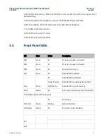
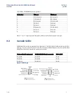
4. LED for R.M (Ring master). When the LED light on, it means that the switch is the ring master of
Redundant Ring.
5. LED for Ring. When the led light on, it means the Redundant Ring is activated.
6. LED for Fault Relay. When the fault occurs, the amber LED will be light on.
7. 10/100Base-T(X) Ethernet ports..
8. LED for Ethernet ports ACT status.
9. LED for Ethernet ports Link status.
3.2
Front Panel LEDs
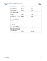
LED
Color
Status
Description
PW1
Green
On
DC power module 1 activated.
PW2
Green
On
DC power module 2 activated.
PW3
Green
On
Power jack activated.
R.M
Green
On
Redundant Ring Master.
Ring
Green
On
Redundant Ring enabled.
Slowly blinking
Redundant Ring topology has problem
Fast blinking
Redundant Ring work normally.
Fault
Amber
On
Fault relay. Power failure or Port down/fail.
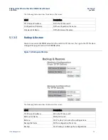
10/100Base-T(X) Fast Ethernet ports
LNK / ACT
Green
On
Port link up.
Blinking
Data transmitted.
Full Duplex
Amber
On
Port works under full duplex.
ACT
LNK

