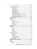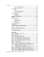
Contents 9
25A Switch Mode Rectifier
NT5C06B / C Installation and User Manual
LVD installation in the shelf ...........................................................................59
Start-up procedure.......................................................................................................60
Factory set voltage limits...............................................................................60
Rectifier power-up .........................................................................................61
HVSD adjustment...........................................................................................62
Float voltage adjustment................................................................................63
Equalize voltage adjustment...........................................................................63
Parallel verification ........................................................................................64
Low voltage disconnect (LVD)........................................................................65
Adjustment for the 50 A LVD unit Rel. 02, 02A, 3 & 3A ................................66
Low voltage alarm (LVA) adjustment..............................................................67
LVD/low voltage disconnect / reconnect (LVDR) adjustment...........................67
Rectifier replacement/add-on procedure .........................................................68
Low voltage disconnect............................................................................................69
Electrical .....................................................................................................................69
Environmental..............................................................................................................69
Storage..........................................................................................................69
DC cabling .....................................................................................................70
Control and monitoring signals.......................................................................70
Operation.......................................................................................................71
Test feature...................................................................................................71
Signal connections.........................................................................................71
Maintenance..............................................................................................................73
Maintenance................................................................................................................73
Rectifier.........................................................................................................73
Filter..............................................................................................................74
Fan cooling ....................................................................................................74
Storage..........................................................................................................74
Power shelf ...................................................................................................74
Low voltage disconnect .................................................................................75
Troubleshooting...........................................................................................................75
Rectifier fail alarm .........................................................................................75
Load sharing ..................................................................................................76
Fan failure .....................................................................................................76
Fan replacement procedure............................................................................76
Low voltage disconnect .................................................................................78
Fault diagnosis...............................................................................................79
Appendix A: NT5C10BF-1 and NT5C10BP ........................................................... 101
Purpose .....................................................................................................................101
Application ................................................................................................................101
FTIP application.........................................................................................................101
Alarms.........................................................................................................102

