Operation 25
25A Switch Mode Rectifier
NT5C06B / C Installation and User Manual
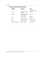
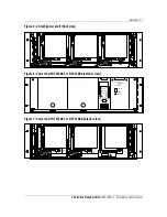
Signal connector
This connector provides control and monitoring signal access to the rectifier.
Refer to the “Signal Connections” section for connection details.
Power interface edge connector
The rectifier AC, DC and chassis ground interface is made through the rear
edge connector. Refer to the “Rectifier and Controller Interface
Connections” section for connection and installation details.
Features
The rectifier provides the following operating, monitoring, measurement and
control features:
Operating features
Remote voltage sensing
Provision is made to extend the sensing leads to the battery or to the
charge/discharge bus (operation without batteries) of the plant. The opening
of either sensing leads will not result in a voltage increase at the rectifier
output terminals.
Current limiting
The rectifier will automatically limit the output current to 17.5 to 20 A
(MPR15) and 25.5 to 30 A (MPR25). Extended periods of operation in the
current limiting mode, and repeated transitions between constant-voltage
operation and constant-current operation have no detrimental effect on the
performance or service life of the rectifier.
The rectifier is capable of starting when connected across a completely
discharged battery without requiring human intervention or operating
protection devices.
Transitions from constant-voltage operation to constant-current operation
and from constant-current to constant-voltage operation will occur
automatically, as determined by the output current. The current limit circuit
will continue working in both the float and equalize modes.
Soft start and walk-in
The output current rises from 10% to 90% in 2 seconds (typically).


