Software Initialization
MVME197LE/D2
3-27
3
Software Initialization
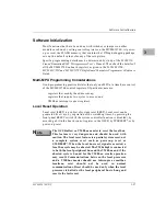
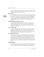
Most functions that have been done with switches or jumpers on other
modules are done by setting control registers on the MVME197LE. At power-
up or reset, the FLASH memory that contains the 197Bug debugging package
sets up the default values of many of these registers.
Specific programming details may be determined by study of the MC88110
Second Generation RISC Microprocessor User’s Manual. Then check the details of
all the MVME197LE onboard registers as given in the MVME197LE,
MVME197DP, and MVME197SP Single Board Computers Programmer’s Reference
Guide.
Multi-MPU Programming Considerations
Good programming practice dictates that only one MPU at a time have control
of the MVME197LE control registers.Of particular note are:
registers that modify the address map;
registers that require two cycles to access; and
VMEbus interrupt request registers.
Local Reset Operation
Local reset (LRST) is a subset of system reset (SRST). Local reset can be
generated five ways: by expiration of the watchdog timer, by pressing the
front panel RESET switch (if the system controller function is disabled), by
asserting a bit in the board control register in the GSCR, by SYSRESET*, or by
power-up reset.
N
ote
The GCSR allows a VMEbus master to reset the local bus.
This feature is very dangerous and should be used with
caution. The local reset feature is a partial system reset, not
a complete system reset such as power-up reset or
SYSRESET*. When the local bus reset signal is asserted, a
local bus cycle may be aborted. The VMEchip2 is connected
to both the local peripheral bus and the VMEbus and if the
aborted cycle is bound for the VMEbus, erratic operation
may result. Communications between the local processor
and a VMEbus master should use interrupts or mailbox
locations; reset should not be used in normal
communications. Reset should be used only when the local
processor is halted or the local peripheral bus is hung and
reset is the last resort.
Summary of Contents for Motorola MVME197LE
Page 2: ...MVME197LE Single Board Computer User s Manual MVME197LE D2 ...
Page 13: ...xii ...
Page 15: ...xiv ...
Page 23: ...Hardware Preparation and Installation 2 2 User s Manual 2 ...
Page 31: ...Hardware Preparation and Installation 2 10 User s Manual 2 ...
Page 38: ...Memory Maps MVME197LE D2 3 7 3 ...
Page 41: ...Operating Instructions 3 10 User s Manual 3 ...
Page 43: ...Operating Instructions 3 12 User s Manual 3 ...
Page 45: ...Operating Instructions 3 14 User s Manual 3 ...
Page 47: ...Operating Instructions 3 16 User s Manual 3 ...
Page 49: ...Operating Instructions 3 18 User s Manual 3 ...
Page 61: ...Functional Description 4 2 User s Manual 4 ...
Page 69: ...Functional Description 4 10 User s Manual 4 ...

