MVME197LE/D23-1
3
OPERATING
INSTRUCTIONS
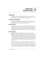
Introduction
This chapter provides the necessary information to use the MVME197LE
VMEmodule in a system configuration. This includes controls and indicators,
memory maps, and software initialization of the module.
Controls and Indicators
The MVME197LE Single Board Computer has two push-botton switches
(ABORT and RESET) and six LED indicators (FAIL, SCON, RUN, LAN, VME,
and SCSI), all located on the front panel of the module.
ABORT Switch S2
When enabled by software, the front panel ABORT switch (S2) generates an
NMI (Non-Maskable Interrupt) type interrupt at a user-programmable level.
It is normally used to abort program execution and return to the 197Bug
debugger. Refer to the VMEchip2 chapter of the MVME197LE, MVME197DP,
and MVME197SP Single Board Computers Programmer’s Reference Guide for more
information.
RESET Switch S3
The RESET switch (S3) will reset all the onboard devices and drive the
SYSRESET* signal if the MVME197LE module is the system controller. The
RESET switch (S3) will reset all the onboard devices, with the exception of the
DCAM and ECDM, if the MVME197LE module is not the system controller.
The VMEchip2 generates the SYSREST* signal. The BusSwitch combines the
local reset and the reset switch to generate a local board reset. Refer to the Reset
Driver section in the VMEchip2 chapter of the MVME197LE, MVME197DP, and
MVME197SP Single Board Computers Programmer’s Reference Guide for more
information.
The BusSwitch receives the reset switch signal, debounces it and combines
with the reset signal from the VMEchip2 to generate a board reset signal.
The VMEchip2 includes both a global and a local reset driver. When the chip
operates as the VMEbus system controller, the reset driver provides a global
system reset by asserting the VMEbus signal SYSRESET*. A SYSRESET* may
be generated by the RESET switch, a power up reset, a watchdog timeout, or
Summary of Contents for Motorola MVME197LE
Page 2: ...MVME197LE Single Board Computer User s Manual MVME197LE D2 ...
Page 13: ...xii ...
Page 15: ...xiv ...
Page 23: ...Hardware Preparation and Installation 2 2 User s Manual 2 ...
Page 31: ...Hardware Preparation and Installation 2 10 User s Manual 2 ...
Page 38: ...Memory Maps MVME197LE D2 3 7 3 ...
Page 41: ...Operating Instructions 3 10 User s Manual 3 ...
Page 43: ...Operating Instructions 3 12 User s Manual 3 ...
Page 45: ...Operating Instructions 3 14 User s Manual 3 ...
Page 47: ...Operating Instructions 3 16 User s Manual 3 ...
Page 49: ...Operating Instructions 3 18 User s Manual 3 ...
Page 61: ...Functional Description 4 2 User s Manual 4 ...
Page 69: ...Functional Description 4 10 User s Manual 4 ...

