General Information
1-4
User’s Manual
1
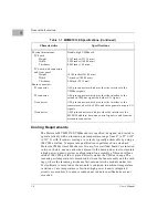
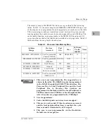
Table 1-1. MVME197LE Specifications (Continued)
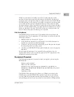
Cooling Requirements
The Motorola MVME197LE VMEmodule is specified, designed, and tested to
operate reliably with an incoming air temperature range from 0° to 55° C (32°
to 131° F) with forced air cooling at a velocity typically achievable by using a
100 CFM axial fan. Temperature qualification is performed in a standard
Motorola VMEsystem 3000 chassis. Twenty-five watt load boards are inserted
in two card slots, one on each side, adjacent to the board under test, to simulate
a high power density system configuration. An assembly of three axial fans,
rated at 100 CFM per fan, is placed directly under the VME card cage. The
incoming air temperature is measured between the fan assembly and the card
cage, where the incoming airstream first encounters the module under test.
Test software is executed as the module is subjected to ambient temperature
variations. Case temperatures of critical, high power density integrated
circuits are monitored to ensure component vendors specifications are not
exceeded.
Characteristics
Specifications
Physical dimensions:
PC board
Height
Width
Thickness
PC board with connectors
and front panel
Height
Width
Thickness
Board connectors:
P1 connector
P2 connector
J1 connector
J2 connector
Double-high VMEboard
9.187 inches (233.35 mm)
6.299 inches (160.00 mm)
0.063 inch (1.60 mm)
10.309 inches (261.85 mm)
7.4 inches (188.00 mm)
0.80 inch (20.32 mm)
A 96-pin connector which provides the interface to the
VMEbus signals.
A 96-pin connector which provides the interface to the
extended VMEbus signals and other I/O signals.
A 20-pin connector which provides the interface to the
remote reset, abort, the LEDs, and three general purpose I/O
signals.
A 249-pin connector which provides the interface to the
MC88110 address, data, and control signals to and from the
mezzanine expansion.
Summary of Contents for Motorola MVME197LE
Page 2: ...MVME197LE Single Board Computer User s Manual MVME197LE D2 ...
Page 13: ...xii ...
Page 15: ...xiv ...
Page 23: ...Hardware Preparation and Installation 2 2 User s Manual 2 ...
Page 31: ...Hardware Preparation and Installation 2 10 User s Manual 2 ...
Page 38: ...Memory Maps MVME197LE D2 3 7 3 ...
Page 41: ...Operating Instructions 3 10 User s Manual 3 ...
Page 43: ...Operating Instructions 3 12 User s Manual 3 ...
Page 45: ...Operating Instructions 3 14 User s Manual 3 ...
Page 47: ...Operating Instructions 3 16 User s Manual 3 ...
Page 49: ...Operating Instructions 3 18 User s Manual 3 ...
Page 61: ...Functional Description 4 2 User s Manual 4 ...
Page 69: ...Functional Description 4 10 User s Manual 4 ...

