Electrical Connections
81
Liebert
®
SRC™ User Manual
6.6 Thermostat Installation and Wiring
NOTICE
Risk of improper thermostat installation. Can cause unit malfunction.
• Installation work must be performed in accordance with the national wiring standards and local
code by authorized personnel only.
• If local electric and building code requires plenum(CMP) cable, use an enclosed, non-
combustible conduit (metal raceway) or FT-6 rated or above cable.
• When using back cable-entry, AWG#22, 3 core shielded wire is recommended.
• When using top or right-side cable entry, AWG#24, 3 core shielded wire is recommended.
• Do not bury the thermostat in the wall. This can damage the temperature sensor.
• Do not install a cable 164 ft (50 m) or longer. This can cause communication errors.
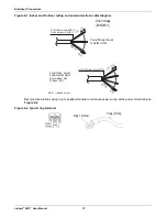
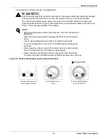
Because the room-temperature sensor is in the thermostat, it should be installed in a place away from
direct sunlight, high humidity, and direct supply of cold air to maintain proper temperature of the space.
Install the thermostat about 5 ft. (1.5 m) above the floor in an area with good air circulation at an average
temperature,
.
Do not install the thermostat where it can be affected by the following:
• Drafts or dead spots behind doors and in corners.
• Hot or cold air from ducts.
• Radiant heat from sun or appliances.
• Concealed pipes or chimneys.
• Uncontrolled areas such as on an outside wall.
The thermostat is equipped with an LCD display and should be installed at the recommended height for
proper view of the display.
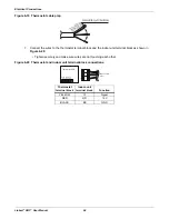
Figure 6-14 Proper and Improper thermostat locations
NOTE
If the distance between the thermostat and the indoor unit is longer than 32 ft
(10 m), use an extension cable.
5feet
(1.5meters)
Direct
Sun ray contact area
no
no
no
yes
Op
era
tio
n u
nit
ZO
N
E
1
2
3
4
Hum
idi
fy
J ET
AUT
O
AU
TO
SW
IN
G
OP
ER
AT
IO
N
FA
N
S P
EE
D
Pr
og
ram
se
t
SU
B F
UN
CT
ION
S E
T T
E M
P
R o
om
Te
mp
HI
MED
LO
He
ate
r
De
fro
st
Filt
er
Pre
hea
t
Ou
t d
oo
r
Ti
m
e
Ti
m
er
On
Se
t no
.
Tim
e
O
ff
0 1
0 3
0 5
0 7
0 9
11
13
15
17
19
2 1
23
Op
era
tio
n u
nit
ZO
N
E
1
2
3
4
Hu
mi
dif
y
J ET
AU
TO
AU
TO
S
W
IN
G
OP
ER
AT
IO
N
FA
N
S P
EE
D
Pro
gra
m s
et
SU
B F
UN
CT
IO
N
SET
T
EM
P
Ro
om
Te
mp
HI
MED
LO
He
ate
r
De
fro
st
Filt
er
Pre
hea
t
Ou
t d
oo
r
Ti
m
e
Ti
m
er
On
S e
t n
o.
Tim
e
O
ff
0
1
0 3
0
5
0 7
0 9
11
13
15
17
19
2 1
2
3
Summary of Contents for Liebert SRC Series
Page 1: ...Liebert SRC User Manual Mini Split Cooling System ...
Page 2: ......
Page 18: ...Safety Symbols Liebert SRC User Manual 8 Page intentionally left blank ...
Page 20: ...Model Number and Nomenclature Liebert SRC User Manual 10 Page intentionally left blank ...
Page 28: ...Product Introduction Liebert SRC User Manual 18 Page intentionally left blank ...
Page 122: ...Troubleshooting Liebert SRC User Manual 112 Page intentionally left blank ...
Page 123: ......


