Piping
69
Liebert
®
SRC™ User Manual
5.5.1.3 Ambient Temperature for Leak Test
If the ambient temperature changed between the time when the pressure was applied and when the
pressure-drop was checked, adjust the results by factoring-in approximately 1.45 psi for each 2°F of
temperature difference.
Correction formula = (Ambient temperature when pressure was applied – Ambient temperature when
pressure drop was checked) x 0.01.
For example:
When pressure (550 psig) was applied, the ambient temperature was 80.6°F. When the pressure drop was
checked 24 hours later (540 psi), the ambient temperature was 68°F.
Therefore, 80.6 – 68 x 0.01 = 0.126. In this case, the pressure drop of 0.126 was due to temperature
difference, and there is no leak in the refrigerant-piping system.
5.5.2
Evacuation
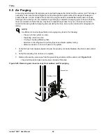
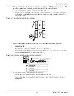
After successfully completing leak testing, use the same hook-up described in
, page
, to
perform the evacuation procedure.
1. Confirm that the “Lo” knob of the manifold valve is open,
.
2. Confirm that the “Hi” know of the manifold valve is closed.
3. Run the vacuum pump until the system is evacuated down to 300 microns, and continue to run the
pump an additional 15 minutes.
4. When appropriate time has elapsed, turn-off the pump and leave the connections secured on the
service valves for 5 minutes.
5. If the system fails to hold 500 microns or less, check all connections for a tight fit and repeat the
evacuation steps.
6. When the correct vacuum is reached, close the “Lo” know of the manifold valve and stop the vacuum
pump.
NOTE
• Be sure to use a manifold valve for air purging. If it is not available, use a
stop valve.
• Be sure that the knob of the 3-way valve is always kept closed.
NOTE
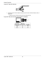
The duration of running the vacuum pump will vary according to pipe length
and pump capacity. Refer to
for accurate time duration.
Table 5-17 Evacuation timing*
Tubing less than 33 ft.
Tubing more than 33 ft.
10 minutes or more
15 minutes or more
* Required time for evacuation when 30-gal/h vacuum pump is used.
Summary of Contents for Liebert SRC Series
Page 1: ...Liebert SRC User Manual Mini Split Cooling System ...
Page 2: ......
Page 18: ...Safety Symbols Liebert SRC User Manual 8 Page intentionally left blank ...
Page 20: ...Model Number and Nomenclature Liebert SRC User Manual 10 Page intentionally left blank ...
Page 28: ...Product Introduction Liebert SRC User Manual 18 Page intentionally left blank ...
Page 122: ...Troubleshooting Liebert SRC User Manual 112 Page intentionally left blank ...
Page 123: ......


