72 Chapter 7 Parallel System & Dual Bus System
NX UPS Single Module And Parallel System 250kVA ~ 800kVA User Manual
Note
You must use the shortest parallel cables to suit the application and must not coil excess. Meanwhile, separate the parallel cables
from the power cables to prevent electrical interferences.
UPS 1
UPS 3
UPS 4
J26
J28
UPS 2
J26
J28
J28
J26
J28
J26
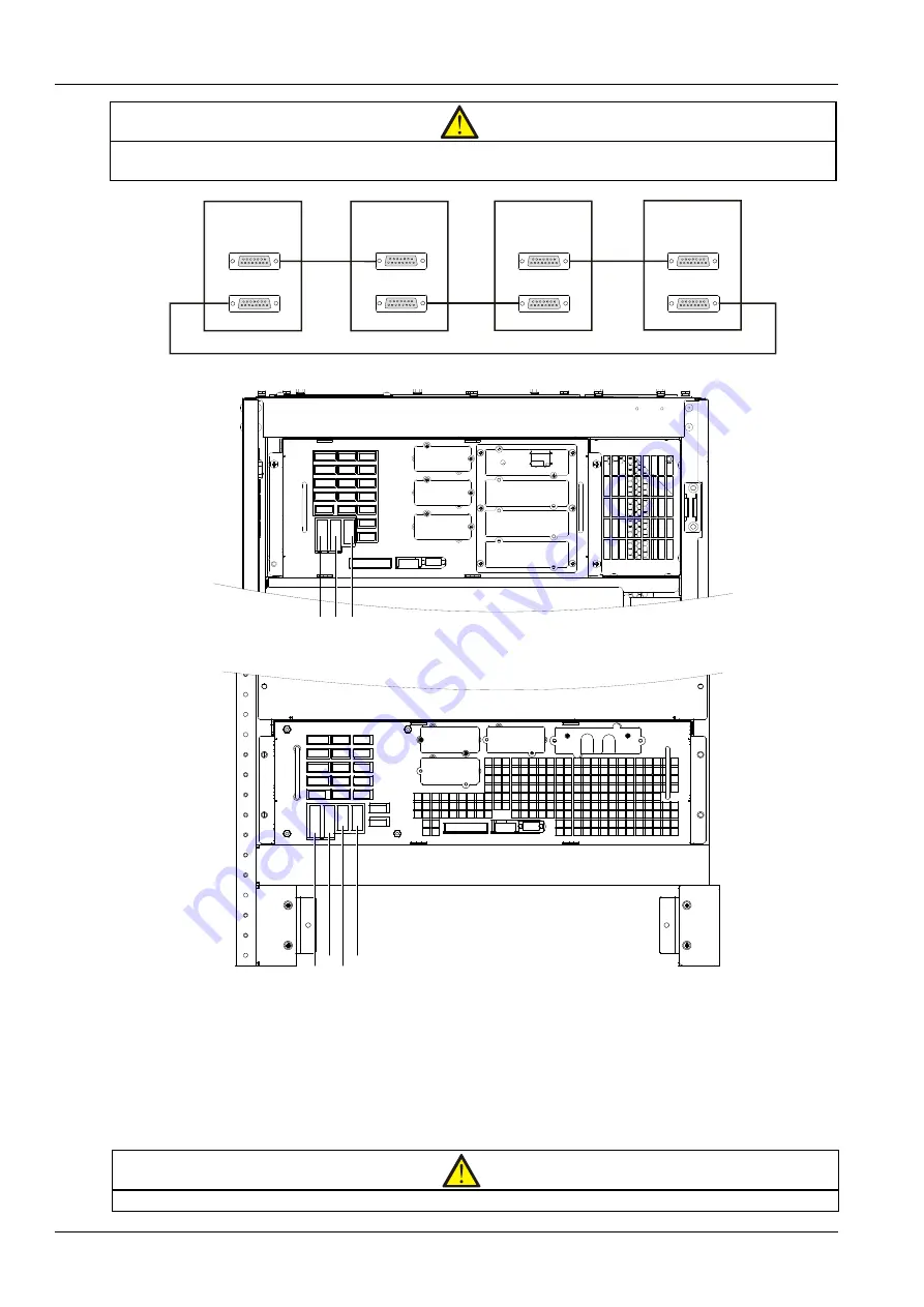
Figure 7-2 Connection of parallel cables of parallel system
J22
J24
J34
J26
J28
J23
J17
J16
J33
J20
J30
J14
J21
J29
J13
J19
J31
J25
J15
J32
Intellislot 1
Intellislot 2
Intellislot 3
RS232
J28 J26 J34
Figure 7-3 Locations of ports J26, J28 and J34 on control module in bypass cabinet (250kVA ~ 400kVA, 600kVA ~ 800kVA)
Intellislot 2
Intellislot 1
Intellislot 3
RS232
J32
J31
J29
J30
J16
J15 J25
J19 J13
J14
J33
J21
J20
J17 J23
J28 J26 J34 J38
J24
J22
J28
J26
J34
J38
Figure 7-4 Locations of ports J26, J28, J34 and J38 on control module in bypass cabinet (500kVA ~ 600kVA E)
7.2.6 Remote EPO
In addition to the EPO switch provided on the operator control and display panel of each UPS module for controlling
the EPO of each module respectively, the parallel system also provides remote EPO function for controlling all UPS
modules to shut down simultaneously from a remote terminal, as shown in Figure 7-5.
Note
1. The remote EPO switch must provide dry contact signal, which is normally open or closed.


