background image

Liebert GXTRT Series                                                                      Installation and User Manual 
1-3 kVA UPS 


Page 19 

9/2005 

Emerson Network Power 


Operation 

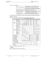
Table 3-1  LED indication 

BATTERY indicator (green) 

It illuminates when the UPS is on battery and the 
battery voltage is not too high, flashes when the 
battery is faulty or the charging voltage is too high 

INVERTER indicator (green) 

It illuminates when the inverter is in normal operation, 
flashes when the inverter is faulty 

BYPASS indicator (green) 

It illuminates when the UPS is on bypass. 

LINE indicator (green) 

It illuminates when the mains input is normal, flashes 
when abnormal, and goes off when it fails 

ALARM indicator (red) 

It is on in the event of a UPS fault, off otherwise. 

 
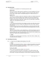
The buzzer and the ten indicators combine to indicate the UPS operating status and faults, as 
illustrated in Table 3-2: 

Table 3-2    Audible alarm and LED indication of UPS operating status and fault

LED number (identified in Figure 3-1) 

S/

Operating status 

10 

Audible alarm 

0%~25% 

load 


 None 

26%~50% 

load 


 None 

3 51%~75% 

load 


 None 

4 76%~100% 

load 


 None 

5 101%~105% 

load 


 None 

Normal 
mode 

>105% load 


Twice every 1s 

0%~25% battery 
capacity 


  Once every 1s 

26%~50% battery 
capacity 


  Once every 3.3s 

51%~75% battery 
capacity 


  Once every 3.3s 

10 

76%~95% battery 
capacity 


  Once every 3.3s 

11 

>96% battery 
capacity 


  Once every 3.3s 

12 

Battery 
mode 

>105% load 


  Twice every 1s 

13 Shortcircuit 

fault 


Continuous 

14 Charger 

fault 


Continuous 

15 Overheating 

fault 


Continuous 

16 

Fan 

failure 


Once every 1s 

17 

Rectifier 

fault 


Continuous 

18 

Inverter 

fault 


¤


 Continuous 

19 Inverter 

overload 


Continuous 

20 

Battery overcharge 
(in Normal mode) 


¤

  None 

21 

Battery overcharge (in Standby 
state) 


¤

  None 

22 No 

battery 


¤

  6 times 

 ON;     depending on other conditions; 

¤

 Flash 


Note 

LED 1 is yellow, LED 6 is red, others are green. 
 

Summary of Contents for GXT-RT series

Page 1: ...accuracy and completeness in this manual Emerson Network Power assumes no responsibility and disclaims all liability for damages resulting from use of this information or for any errors or omissions Emerson Network Power pursues a policy of continuous product development and reserves the right to change the equipment design without notice Copyright 2005 by Emerson Network Power All rights reserved...

Page 2: ...s Battery Module 13 2 4 Rack Installation 14 2 4 1 Installing Single Power Module 14 2 4 2 Installing Power Module Plus Battery Module 15 2 5 Cable Connection 15 2 5 1 Connecting Battery Cable 15 2 5 2 Connecting Input And Output Cables 16 2 5 3 Connecting Communication Cable 16 3 Operation 18 3 1 Operator Control And Display Panel 18 3 2 Operation Mode 20 3 3 Operating Instructions 20 3 3 1 Turni...

Page 3: ...ns Never dispose of the battery in a fire as it may explode when exposed to flame Do not apply pure inductive load to the UPS The UPS has its own energy source i e a battery therefore the output terminal of the UPS may carry live voltage even when the UPS is not connected to the AC mains Before moving or re wiring the UPS please disconnect the mains source and make sure the UPS is completely shut ...

Page 4: ...al UPS operation and adequate autonomy time Only an Emerson authorized technician is permitted to replace the battery In replacement of battery or battery module please use the same model and number of battery or battery module It is recommended to place battery at a place with controlled ambient temperature The rated battery performance is available at 25 degree Celsius Do not open or damage the ...

Page 5: ... Emerson Network Power Commonly Used Notations Description of commonly used notations Some or all of the following Notations may be used in this manual and may appear in your application process Therefore all users should be familiar with them and understand their explanations ...

Page 6: ...conversion topology structure to achieve a high input power factor up to 0 99 greatly reducing its contamination to the power grids z With a wide range of input voltages and an output immune to the mains interference the product is suitable even for areas with unstable mains power supply It is an environmentally efficient energy source z With a wide range of input frequencies the product can be we...

Page 7: ...harger Extended back up time 3kVA extended back up time power module GXT3000L RT With an 8A internal charger Front panel appearance All models of power modules have the same front panel which provides ON Alarm silence button OFF button and LED indication as shown in Figure 1 1 Figure 1 1 Front panel of power module Rear panel appearance The power module s rear panel differs with the model as shown...

Page 8: ...GXT2000 BAT and GXT3000 BAT as shown in Table 1 2 Users can confirm the module model by checking the nameplate on the enclosure Table 1 2 Battery module models Module name Model Remark 72V 7 2Ah battery module GXT2000 BAT 72V with a 6 12V 7 2Ah internal battery 72V 9 0Ah battery module GXT3000 BAT 72V with a 6 12V 9Ah internal battery Front panel and rear panel appearances The GXT2000 BAT and GXT3...

Page 9: ...pes and configurations Configuration UPS type Module Model Qty Remark 1kVA standard UPS Power module GXT1000 RT 1 The UPS has only one power module Power module GXT2000 RT 1 2kVA standard UPS Battery module GXT2000 BAT 1 Power module GXT3000 RT 1 Standard 3kVA standard UPS Battery module GXT3000 BAT 1 The UPS consists of a power module and a battery module 1kVA extended back up time UPS Power modu...

Page 10: ... UPS operates in Battery mode Inverter an important back end processing functional module of the UPS In Normal mode the inverter utilizes the DC output of the PFC circuit and inverts it into precise regulated sinewave AC power In Battery mode the inverter receives its required energy from the battery through the DC DC converter Bypass this module plays a very important role in enhancing the UPS re...

Page 11: ...e DB9 can be used for RS232 serial communication and dry contact communication Users can use the accessory UPS monitoring software to monitor the UPS through the DB9 port SNMP card slot The SNMP card slot is designed for installing the SNMP card option which enables users to monitor the UPS over network It is also used for auto shut down of computers in a network Please consult Emerson representat...

Page 12: ...RT GXT3000 RT and GXT3000L RT power modules is 16A 2 Only long back up time power modules are delivered with a battery connection cable a 1 8m long cable with OT terminals attached to one end and a connector attached to the other which is a 3 pin one for GXT1000L RT module and a 5 pin one for GXT2000 RT and GXT3000L RT modules Table 2 2 Battery module accessory list Accessory Quantity Unit Tower i...

Page 13: ...igure 2 1 Making base 2 As shown in the left figure below move the two bases to appropriate positions and put the power module gently down on the bases then push the power module gently in the directions shown in the right figure below to position it evenly on the two bases Figure 2 2 Positioning power module 2 3 2 Installing Power Module Plus Battery Module Use the following steps to install the ...

Page 14: ...battery module These power modules include GXT1000 RT GXT1000L RT GXT2000L RT and GXT3000L RT 1 Take out the pair of brackets delivered with the power module remove the four flat screws M4 8 on both sides of the module as shown in Figure 2 5 and fix the brackets onto both sides of the module using the flat screws as shown in Figure 2 6 Figure 2 5 Removing flat screws Figure 2 6 Installing brackets...

Page 15: ...e Power module plus battery module system Take out the battery connection cable delivered with the battery module plug one end of the cable into the external battery socket on the rear panel of the power module and the other end into any battery socket on the rear panel of the battery module Long back up time system Warning 1 Batteries have represent a potentially dangerous source of energy Only p...

Page 16: ... into the output socket of the power module 2 5 3 Connecting Communication Cable DB9 communication port Where users need to use the single UPS monitoring software delivered with the power module to monitor the UPS in communication cable connection just locate the RS232 cable delivered with the power module and insert the two cable plugs respectively into the RS232 port of the computer and the DB9 ...

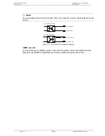
Page 17: ...ry contact voltage shall not exceed 30Vdc R Dry contact signal input Dry contact signal output Common GND Open emitter Open collector OFF level input Figure 2 10 Dry contact port schematic diagram SNMP card slot For those that use the SNMP card to monitor the UPS please refer to the SNMP Card User Manual for the SNMP card installation and communication connection instructions ...

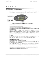
Page 18: ...when the buzzer beeps every 3 3s pressing and holding the ON Alarm silence button for one second can silence the buzzer 3 Initiate battery test In Normal mode pressing and holding the ON Alarm silence button for one second can initiate the battery test Note The alarm silencing function of the ON Alarm silence button is valid only for the one beep per 3 3s audible alarm in Battery mode and invalid ...

Page 19: ...llustrated in Table 3 2 Table 3 2 Audible alarm and LED indication of UPS operating status and faults LED number identified in Figure 3 1 S N Operating status 1 2 3 4 5 6 7 8 9 10 Audible alarm 1 0 25 load None 2 26 50 load None 3 51 75 load None 4 76 100 load None 5 101 105 load None 6 Normal mode 105 load Twice every 1s 7 0 25 battery capacity Once every 1s 8 26 50 battery capacity Once every 3 ...

Page 20: ...s failure or mains voltage frequency outside the specifications when the UPS is in Bypass mode the UPS will shut down and cease supplying power to the load Battery mode In the event of a mains failure or mains voltage frequency outside the specifications when the UPS is in Normal mode the rectifier and charger will become inoperative and the battery will begin to discharge and supply the load thro...

Page 21: ...PS inverter turns off the UPS ceases output and transfers to standby state the LINE indicator and LED 5 are on In standby state the UPS is not completely powered down To completely power down the UPS disconnect the mains input to the UPS 2 Completely power down the UPS from Battery mode Just hold and press the OFF button for one second and the UPS will shut down and cease output 3 Completely power...

Page 22: ...ure 1 6 which is provided for the IEC output socket No fuse is provided for the output terminal block Procedures for replacing the fuse are as follows 1 Remove the fuse holder from the rear panel of the power module by turning a flat head screwdriver counter clockwise 2 Take out the fuse from the fuse holder and put a new one in it 3 Replace the fuse holder by turning the flat head screwdriver clo...

Page 23: ...he AC input overcurrent protection switch button to reconnect the mains input to the UPS 3 The LINE LED flashes or is off The mains voltage or frequency is outside the specifications Check the input voltage frequency and the AC input overcurrent protection switch Disconnect the load to prevent UPS shut down from causing any damage when the battery voltage reaches the end of discharge point 4 The A...

Page 24: ...e seek technical assistance from local Emerson customer service office 11 The INVERTER LED flashes the ALARM LED lights up the buzzer beeps Inverter fault Seek technical assistance from local Emerson customer service office 12 The ALARM LED and LED 5 lights up the buzzer beeps Rectifier fault Seek technical assistance from local Emerson customer service office 13 The ALARM LED and LED 2 lights up ...

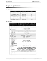
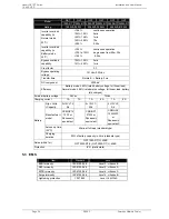
Page 25: ... Vac Voltage range 1 176 288Vac full load 2 176Vac linear derating 3 120Vac half load Frequency 50Hz 10 Input Power factor 0 99 conditions rated voltage full pure resistive load fully charged battery Output system 1 phase plus PE Power factor 0 7 Voltage 220 Vac 230 Vac 240 Vac 2 Line regulation 2 0 100 linear load Output Load regulation 2 0 100 linear load Voltage harmonic distortion rated input ...

Page 26: ...rated battery voltage full linear load Normal mode 88 rated mains voltage full linear load battery fully charged External battery voltage 36Vdc 72Vdc Charging current 1A 7A 1A 8A 1A 8A Qty Volts Capacity 3 12V 7 2 Ah 6 12V 7 2Ah 6 12V 9 Ah Manufacturer model CSB GP12 72F2 or Panasonic equivalent CSB GP1 272F2 or Panasonic equivalent CSB HRL 1234WF2 or Panasonic equivalent Autonomy time 25 C 5min a...

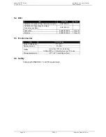
Page 27: ...mitation of voltage changes voltage fluctuations and flicker EN61000 3 3 Conduction EN IEC62040 2 Class B Emission EN IEC62040 2 Class B 5 5 Environmental Item Normal range Ambient temperature 0 C 40 C Relative humidity 5 95 Altitude Lower than 1500m no derating 1500m 3000m 1 derating for every 100m rise Storage temperature 25 C 55 C excluding battery 5 6 Safety Comply with EN62040 1 1 and CE requ...

Reviews: