background image

Maintenance and Troubleshooting

September 2013

7-7

Table 7-2. DIP Switch Configuration

(1)

Operational Mode

Switch Position

Multidrop Loop

UP

Point-to-Point Loop

DOWN

1. Refer to figure 7-4 for switch location.

Replacing the PWB Assembly and Setting
the DIP Switch  

1.  Apply silicone lubricant to the pressure sensor
O-rings (key 40) and install them on the pressure
sensor bosses in the module base assembly.

2.  Properly orient the PWB assembly (key 50) as you
install it into the module base. The two electrical leads
from the I/P converter (key 41) must guide into their
receptacles in the PWB assembly and the pressure
sensor bosses on the module base must fit into their
receptacles in the PWB assembly.

3.  Push the PWB assembly (key 50) into its cavity in
the module base.

4.  Install and tighten three screws (key 33) to a torque
of 1 N

m (10.1 lbf

in).

5.  Set the DIP switch on the PWB assembly
according to table 7-2.

Note

For the digital valve controller to
operate with a 4 to 20 mA control
signal, be sure the DIP switch is in the
point-to-point loop position, i.e.,
switch in down position.

6.  Reassemble the module base to the housing by
performing the Replacing the Module Base procedure.

7.  Setup and calibrate the digital valve controller.

Pneumatic Relay

Refer to figures 8-2 through 8-9 for key number
locations. The pneumatic relay (key 24) is located on
the front of the module base.

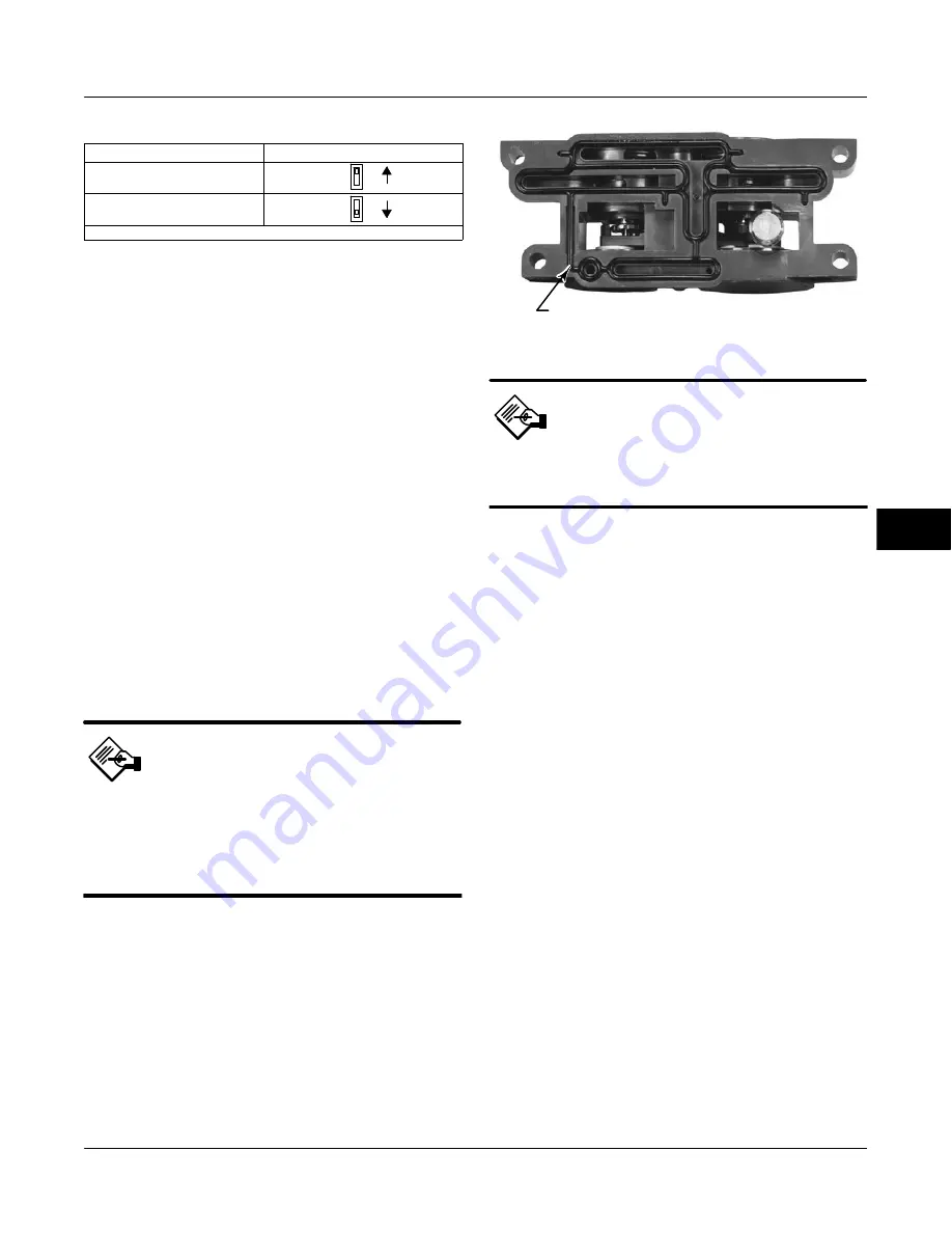
Figure 7-5. Pneumatic Relay Assembly

W8074

RELAY SEAL

Note

After relay submodule replacement,
calibrate the digital valve controller
to maintain accuracy specifications.

Removing the Pneumatic Relay  

1.  Loosen the four screws that attach the relay 
(key 24) to the module base. These screws are
captive in the relay.

2.  Remove the relay.

Replacing the Pneumatic Relay  

1.  Visually inspect the holes in the module base to
ensure they are clean and free of obstructions. If
cleaning is necessary, do not enlarge the holes.

2.  Apply silicone lubricant to the relay seal and
position it in the grooves on the bottom of the relay as
shown in figure 7-5. Press small seal retaining tabs
into retaining slots to hold relay seal in place.

3.  Position the relay (with shroud) on the module
base. Tighten the four screws, in a crisscross pattern,
to a final torque of 2 N

m (20.7 lbf

in).

4.  Using the Field Communicator, verify that the value
for the parameter Relay matches the relay type
installed.

5.  After replacing the relay and verifying the relay
type, calibrate travel or perform touch-up calibration to
maintain accuracy specifications

Gauges, Pipe Plugs, or Tire Valves  

Depending on the options ordered, the DVC6000 will
be equipped with either gauges (key 47), pipe plugs
(key 66), or tire valves (key 67). Single-acting direct
instruments will also have a screen (key 236, figure
8-6). These are located on the top of the module base
next to the relay.

7

Summary of Contents for Fisher FIELDVUE DVC6000

Page 1: ...of this publication are presented for informational purposes only and while every effort has been made to ensure their accuracy they are not to be construed as warranties or guarantees express or implied regarding the products or services described herein or their use or applicability All sales are governed by our terms and conditions which are available upon request We reserve the right to modify...

Page 2: ......

Page 3: ...struction Manual D102794X012 September 2013 Fisherr FIELDVUEt DVC6000 Digital Valve Controllers This manual applies to Instrument Level AC HC AD PD HC AD PD ODV AC Device Type 03 03 07 Device Revision 1 2 2 Hardware Revision 1 1 1 Firmware Revision 2 6 7 9 10 11 7 9 10 11 DD Revision 4 8 1 Refer to Related Documents on page 1 3 for other documents containing information related to DVC6000 digital ...

Page 4: ...3 Configured Pressure 1 2 1 4 5 6 B 1 2 2 1 2 2 8 B Control Mode Hot Key 2 1 A Integrator Saturated Hi Enable 1 2 4 4 1 8 I 1 2 1 2 4 B Integrator Saturated Lo Enable 1 2 4 4 2 8 I Critical NVM Shutdown 1 2 3 1 3 4 12 C Last AutoCalibration Status 1 2 5 9 1 6 H Custom Characterization Table 1 2 2 4 4 C Last Calibration Type 1 2 5 9 2 6 H Cutoff Hi 1 2 3 4 7 3 12 G Loop Current Validation Enable 6 ...

Page 5: ...el Deviation Time 1 2 3 4 4 3 10 E Pressure Units 1 2 5 2 1 6 G Travel Limit Cutoff Hi Enable 1 2 3 4 7 1 12 F Protection Hot Key 3 1 A Travel Limit Cutoff Lo Enable 1 2 3 4 7 2 12 F 1 2 1 5 4 B Travel Limit Hi 1 2 3 4 7 6 12 G Raw Travel Input 3 6 7 4 H 1 2 2 2 2 4 10 C Reference Voltage Shutdown 1 2 3 1 3 7 12 C Travel Limit Lo 1 2 3 4 7 7 12 G Relay Adjust 1 3 3 3 E 1 2 2 2 2 5 10 C Relay Type ...

Page 6: ...ximum Recorded Temperature 4 Mininum Recorded Temperature 5 Cycle Counter 6 Travel Accumulator 7 Raw Travel Input 8 View Number of Days Powered Up 9 Number of Power Ups Pressure 1 Pressure A 2 Pressure B 3 A Minus B 4 Supply Service Tools 1 Alert Conditions 2 Status 3 Device Record 4 Stroke Valve 5 Partial Stroke Test Overview 1 Analog In 2 Setpoint 3 Travel 4 Drive Signal 5 Pressure 6 Variables 7...

Page 7: ... 3 Travel Alert Hi Point 4 Travel Alert Lo Point Travel Limit Cutoff Alerts 1 Travel Limit Cutoff Hi Enable 2 Travel Limit Cutoff Lo Enable 3 Cutoff Hi 4 Cutoff Lo 5 Change Cutoffs 6 Travel Limit Hi 7 Travel Limit Lo 8 Change Travel Limits Integrator Saturation 1 Integrator Sat Hi Enable 2 Integrator Sat Lo Enable 3 Integral Limit 4 Integral Dead Zone Travel Deviation Alert 1 Travel Deviation Aler...

Page 8: ...izard 1 1 1 1 3 D Firmware Revision 2 1 3 3 G Travel Integral Gain 1 2 3 2 3 6 F Hardware Revision 2 1 4 3 G Travel Integral Enable 1 2 3 2 2 6 F HART Tag 1 2 1 1 3 D Travel MLFB Gain 1 1 2 3 1 4 6 C HART Universal Revision 2 1 1 3 G 1 2 3 2 1 4 6 E Input Characterization 1 2 3 6 4 F Travel Pressure Select 1 1 2 2 1 4 C Instrument Level 2 1 5 3 H 1 2 3 1 4 F Instrument Mode Hot Key 1 1 B Travel Pr...

Page 9: ...1 1 indicates fast key sequence to reach menu This menu is available by pressing the left arrow key from the previous menu 1 1 1 1 1 1 1 2 1 2 1 2 1 1 2 3 2 1 3 2 1 1 1 Press Actuator 1 Tvl Press Select 2 Pressure Units 3 Max Supply Press 4 Actuator Style 5 Feedback Conn 6 Tvl Sensor Motion 7 Valve Style 8 Zero Pwr Cond Tuning Calib 1 Tvl Tuning Set 2 Press Tuning Set 3 Relay Adjust 4 Auto Travel ...

Page 10: ... CONTROLLER POWERS PLANTWEB BY CAPTURING AND DELIVERING VALVE DIAGNOSTIC DATA COUPLED WITH VALVELINKt SOFTWARE THE DVC6000 PROVIDES USERS WITH AN ACCURATE PICTURE OF VALVE PERFORMANCE INCLUDING ACTUAL STEM POSITION INSTRUMENT INPUT SIGNAL AND PNEUMATIC PRESSURE TO THE ACTUATOR USING THIS INFORMATION THE DIGITAL VALVE CONTROLLER DIAGNOSES NOT ONLY ITSELF BUT ALSO THE VALVE AND ACTUATOR TO WHICH IT ...

Page 11: ...uction and Specifications September 2013 1 1 Section 1 Introduction Scope of Manual 1 2 Conventions Used in this Manual 1 2 Description 1 3 Specifications 1 3 Related Documents 1 3 Educational Services 1 4 1 ...

Page 12: ...e help or documentation Do not install operate or maintain a DVC6000 digital valve controller without being fully trained and qualified in valve actuator and accessory installation operation and maintenance To avoid personal injury or property damage it is important to carefully read understand and follow all of the contents of this manual including all safety cautions and warnings If you have any...

Page 13: ... DVC6000 digital valve controller You can obtain general information concerning software revision level messages tag descriptor and date Diagnostic information is available to aid you when troubleshooting Input and output configuration parameters can be set and the digital valve controller can be calibrated Refer to table 1 1 for details on the capabilities of each diagnostic tier Using the HART p...

Page 14: ...Signal Converter with FIELDVUE Digital Valve Controllers Supplement to HART Communicating Fisher FIELDVUE Instrument Instruction Manuals D103267X012 Hot Swap Procedure Supplement to HART Communicating Fisher FIELDVUE DVC5000 Obsolete Product and DVC6000 Digital Valve Controllers Instruction Manuals D103264X012 Implementation of Lock in Last Strategy Supplement to Fisher FIELDVUE DVC6000 and DVC620...

Page 15: ...ded 0 3 bar 5 psi higher than maximum actuator requirements up to maximum supply pressure Maximum 10 bar 145 psig or maximum pressure rating of the actuator whichever is lower Medium Air or Natural Gas Air Supply pressure must be clean dry air that meets the requirements of ISA Standard 7 0 01 Natural Gas Natural gas must be clean dry oil free and noncorrosive H2S content should not exceed 20 ppm ...

Page 16: ...s Classifications and Special Instructions for Safe Use and Installation in Hazardous Locations in section 2 and Appendix B Pollution Degree 2 Overvoltage Category III per ANSI ISA 82 02 01 IEC 61010 1 Mod Electrical Housing CSA Type 4X IP66 FM Type 4X IP66 ATEX IP66 IECEx IP66 Other Classifications Certifications Gas Certified Single Seal Device CSA FM ATEX and IECEx FSETAN Federal Service of Tec...

Page 17: ...s are defined in ISA Standard 51 1 Process Instrument Terminology 1 3 conductor shielded cable 22 AWG minimum wire size is required for connection between base unit and feedback unit Pneumatic tubing between base unit output connection and actuator has been tested to 91 meters 300 feet At 15 meters 50 feet there was no performance degradation At 91 meters there was minimal pneumatic lag 2 The pres...

Page 18: ...II III Division 1 GP A B C D E F G per drawing GE42818 Natural Gas Approved Vmax 30 VDC Imax 226 mA Ci 5 nF Li 0 55 mH Pi 1 4 W Voc 30 VDC Isc 12 mA Ca 66 nF La 246 mH Po 86 mW T5 Tamb 80 C T6 Tamb 75 C Type 4X IP66 Single Seal Device Explosion proof Class I Division 1 GP B C D Natural Gas Approved T5 Tamb 80 C T6 Tamb 75 C Type 4X IP66 Single Seal Device Class I Division 2 GP A B C D Class II Div...

Page 19: ... Division 1 GP A B C D E F G per drawing GE42819 Natural Gas Approved Vmax 30 VDC Imax 226 mA Ci 5 nF Li 0 55 mH Pi 1 4 W Voc 9 6 VDC Isc 3 5 mA Ca 3 6 uF La 100 mH Po 8 4 mW T5 Tamb 80 C T6 Tamb 75 C Type 4X IP66 Single Seal Device XP Explosion proof Class I Division 1 GP B C D NI Non incendive Class I Division 2 GP A B C D DIP Dust Ignition proof Class II III Division 1 GP E F G S Suitable for U...

Page 20: ...x ia IIC T5 T6 Ga Dust Ex ia IIIC T85 C Ta 76 C T89 C Ta 80 C Da Per drawing GE60771 Natural Gas Approved Ui 30 VDC Ii 226 mA Ci 5 nF Li 0 55 mH Pi 1 4 W Uo 9 6 VDC Io 3 5 mA Co 3 6 uF Lo 100 mH Po 8 4 mW T5 Tamb 80 C T6 Tamb 75 C IP66 Single Seal Device II 2 G Flameproof Gas Ex d IIC T5 T6 Gb Natural Gas Approved T5 Tamb 85 C T6 Tamb 80 C IP66 Single Seal Device II 3 G Type n Gas Ex nC IIC T5 T6 ...

Page 21: ...Single Seal Device DVC6005 Intrinsically Safe Gas Ex ia IIC T5 T6 per drawing GE42990 Natural Gas Approved Ui 30 VDC Ii 226 mA Ci 5 nF Li 0 55 mH Pi 1 4 W Uo 9 6 VDC Io 3 5 mA Ca 3 6 uF La 100 mH Po 8 4 mW T5 Tamb 80 C T6 Tamb 75 C IP66 Single Seal Device Flameproof Gas Ex d IIC T5 T6 Natural Gas Approved T5 Tamb 80 C T6 Tamb 75 C IP66 Single Seal Device Type n Gas Ex nC IIC T5 T6 Natural Gas Appr...

Page 22: ...DVC6000 Digital Valve Controllers September 2013 1 12 1 ...

Page 23: ...ing 2 13 Pipestand Mounting 2 13 DVC6015 on Sliding Stem Actuators up to 4 inches travel 2 13 DVC6025 on Long Stroke Sliding Stem Actuators 4 to 24 inches travel and Rotary Actuators 2 15 DVC6035 on Quarter Turn Actuators 2 16 67CFR Filter Regulator Integral Mounted Regulator 2 18 Yoke Mounted Regulator 2 18 Casing Mounted Regulator 2 18 Pneumatic Connections Supply Connections 2 19 Output Connect...

Page 24: ...on Connections 2 29 Wiring Practices Control System Requirements 2 30 HART Filter 2 30 Voltage Available 2 31 Compliance Voltage 2 32 Maximum Cable Capacitance 2 33 Installation in Conjunction with a Rosemount 333 HART Tri Loop HART to Analog Signal Converter 2 33 2 ...

Page 25: ...ing of this controller refer to page 2 22 If installing this into an existing application also refer to the WARNING at the beginning of the Maintenance section of this instruction manual Check with your process or safety engineer for any additional measures that must be taken to protect against process media WARNING To avoid static discharge from the plastic cover when flammable gases or dust are ...

Page 26: ...maximum working pressure of the natural gas supply shall be limited to 145 psi 2 When product is used with natural gas as the pneumatic medium the product shall not be permitted in a Class I Division 2 Group A B C D location without the proper venting installation as per the manufacturer s instruction manual 3 The apparatus enclosure contains aluminum and is considered to constitute a potential ri...

Page 27: ...itional approval information and figure B 15 for typical ATEX Type n nameplates IECEx Conditions of Certification Intrinsically Safe Type n Flameproof Ex ia Ex nC Ex nA Ex d 1 Warning Electrostatic charge hazard Do not rub or clean with solvents To do so could result in an explosion Ex nC Ex nA Ex d 2 Do not open while energized Refer to table 1 7 for additional approval information figures B 16 a...

Page 28: ...6010 digital valve controller mounts on sliding stem actuators with up to 102 mm 4 inch travel Figure 2 1 shows a typical mounting on an actuator with up to 51 mm 2 inch travel Figure 2 2 shows a typical mounting on actuators with 51 to 102 mm 2 to 4 inch travel For actuators with greater than 102 mm 4 inch travel see the guidelines for mounting a DVC6020 digital valve controller Note Do not use t...

Page 29: ...position of the feedback arm key 79 on the digital valve controller to the no air position by inserting the alignment pin key 46 through the hole on the feedback arm as follows For air to open actuators i e the actuator stem retracts into the actuator casing or cylinder as air pressure to the casing or lower cylinder increases insert the alignment pin into the hole marked A For this style actuator...

Page 30: ...ve controllers use a cam designed for linear response and roller as the feedback mechanism Figure 2 4 shows an example of mounting on sliding stem actuators with travels from 4 inches to 24 inches Some long stroke applications will require an actuator with a tapped lower yoke boss Figures 2 5 and 2 6 show the DVC6020 mounted on rotary actuators As shown in figure 2 5 two feedback arms are availabl...

Page 31: ...gure 2 4 FIELDVUE DVC6020 Digital Valve Controller Mounted on Long Stroke Sliding Stem Actuator TYPICAL MOUNTING WITH SHORT FEEDBACK ARM FISHER 1052 SIZE 33 ACTUATOR SHOWN TYPICAL MOUNTING WITH LONG FEEDBACK ARM FISHER 1061 SIZE 30 68 ACTUATOR SHOWN 29B2094 A DOC 29B1672 A DOC MOUNTING ADAPTOR CAP SCREW HEX SOCKET CAM MACHINE SCREW MACHINE SCREW CAP SCREW HEX SOCKET CAM Figure 2 5 FIELDVUE DVC6020...

Page 32: ...on the cam to attain alignment MOUNTING ADAPTER FEEDBACK ARM ASSEMBLY BIAS SPRING ARM ASSEMBLY PIN ARM ASSEMBLY MOUNTING BRACKET Figure 2 7 Locating Adjustment Arm Pin in Feedback Arm of a FIELDVUE DVC6020 Digital Valve Controller DVC6030 on Quarter Turn Actuators If ordered as part of a control valve assembly the factory mounts the digital valve controller on the actuator makes pneumatic connecti...

Page 33: ... the 10 30 position as shown in figure 2 9 If increasing pressure from the digital valve controller output A rotates the potentiometer shaft counterclockwise as viewed from the back of the instrument mount the travel indicator assembly such that the arrow is in the 7 30 position as shown in figure 2 10 Note ValveLink software and the Field Communicator use the convention of clockwise figure 2 9 an...

Page 34: ...ion and Movement if Clockwise Orientation is Selected for Travel Sensor Motion in ValveLink Software or the Field Communicator 19B3879 A DOC 2 STARTING POSITION OF THE TRAVEL INDICATOR ASSEMBLY IF INCREASING PRESSURE FROM OUTPUT A DRIVES THE INDICATOR CLOCKWISE THE POTENTIOMETER SHAFT WILL ROTATE COUNTERCLOCKWISE AS VIEWED FROM THE BACK OF THE FIELDVUE INSTRUMENT STARTING POSITION OF TRAVEL INDICA...

Page 35: ...ex head screws loosely attach the base unit to the pipestand with the mounting bracket Position the second standoff then using the remaining 101 6 mm 4 inch hex head screws securely fasten the base unit to the pipe stand 10C1796 A Doc Figure 2 12 FIELDVUE DVC6005 Base Unit with Mounting Bracket Rear View DVC6015 on Sliding Stem Actuators Up to 102 mm 4 Inches of Travel If ordered as part of a cont...

Page 36: ...ion by inserting the alignment pin key 46 through the hole on the feedback arm as follows For air to open actuators i e the actuator stem retracts into the actuator casing or cylinder as air pressure to the casing or lower cylinder increases insert the alignment pin into the hole marked A For this style actuator the feedback arm rotates counterclockwise from A to B as air pressure to the casing or...

Page 37: ... is installed on the remote feedback unit before beginning the mounting procedure Refer to figures 2 4 2 5 and 2 6 for parts locations Refer to the following guidelines when mounting on sliding stem actuators with 4 to 24 inches of travel or on rotary actuators 1 Isolate the control valve from the process line pressure and release pressure from both sides of the valve body Shut off all pressure li...

Page 38: ...e mounting kit instructions STARTING POSITION OF THE TRAVEL INDICATOR ASSEMBLY IF INCREASING PRESSURE FROM OUTPUT A DRIVES THE INDICATOR CLOCKWISE THE POTENTIOMETER SHAFT WILL ROTATE COUNTERCLOCKWISE AS VIEWED FROM THE BACK OF THE INSTRUMENT STARTING POSITION OF THE TRAVEL INDICATOR ASSEMBLY IF INCREASING PRESSURE FROM OUTPUT A DRIVES THE INDICATOR COUNTERCLOCKWISE THE POTENTIOMETER SHAFT WILL ROT...

Page 39: ...tor or spacer as described in the mounting kit instructions 6 Attach the mounting bracket to the remote feedback unit 7 Position the remote feedback unit so that the pin on the travel indicator engages the slot in the feedback arm and that the bias spring loads the pin as shown in figure 2 11 Attach the remote feedback unit to the actuator or positioner plate 8 If a travel indicator scale is inclu...

Page 40: ...lator Yoke Mounted Regulator Mount the filter regulator with 2 cap screws to the pre drilled and tapped holes in the actuator yoke Thread a 1 4 inch socket head pipe plug into the unused outlet on the filter regulator The O ring is not required Casing Mounted Regulator Use the separate 67CFR filter regulator casing mounting bracket provided with the filter regulator Attach the mounting bracket to ...

Page 41: ...emote venting of the unit re evaluating the hazardous area classification ensuring adequate ventilation and the removal of any ignition sources For information on remote venting of this controller refer to page 2 22 Severe personal injury or property damage may occur from an uncontrolled process if the instrument supply medium is not clean dry oil free and noncorrosive While use and regular mainte...

Page 42: ...proval label shown in figure 2 17 The Natural Gas Certified Single Seal device option simplifies conduit sealing requirements Read and follow all local regional and federal wiring requirements for natural gas installations Contact your Emerson Process Management sales office for information on obtaining a Natural Gas Certified Single Seal DVC6000 digital valve controller Supply pressure must be cl...

Page 43: ...onnect OUTPUT B to the actuator diaphragm casing Double Acting Actuators DVC6000 digital valve controllers on double acting actuators always use relay A With no input current OUTPUT A is at 0 pressure and OUTPUT B is at full supply pressure when the relay is properly adjusted To have the actuator stem extend from the cylinder with increasing input signal connect OUTPUT A to the upper actuator cyli...

Page 44: ...d by connecting the unused output port from the DVC6000 to the pneumatic line between the solenoid valve and the actuator as shown in figure 2 19 When single acting direct relay C is installed the unused output port is port B When single acting reverse relay B is used the unused port is port A Note Solenoid valve testing is only available for instrument level PD and ODV Note This application is ca...

Page 45: ...d 8 5 The vent connection is 3 8 NPT internal At a minimum 12 7 mm 1 2 inch tubing should be used when installing a remote vent to prevent excessive pressure from building up under the cover To connect a remote vent to DVC6020 digital valve controllers replace the standard mounting bracket key 74 figures 8 3 and 8 5 with the vent away bracket key 74 Install a pipe plug in the vent away mounting br...

Page 46: ...ent output to the LOOP screw terminal in the terminal box Connect the control system output card negative or return wire to the LOOP screw terminal SAFETY GROUND LOOP LOOP EARTH GROUND TALK TALK 39B3399 B Sheet 2 Figure 2 20 FIELDVUE DVC6000 Digital Valve Controller Terminal Box WARNING Personal injury or property damage caused by fire or explosion can result from the discharge of static electrici...

Page 47: ...inal box cap see figure 2 16 3 If necessary install conduit between the feedback unit and the base unit following applicable local and national electrical codes Route the 3 conductor shielded cable between the two units refer to figure 2 21 4 Connect one wire of the 3 conductor shielded cable between terminal 1 on the feedback unit and terminal 1 on the base unit 5 Connect the second wire of the 3...

Page 48: ...ox of the DVC6005 contains an additional 30 kOhm fixed resistor that may be added to the circuit This brings the total resistance up to the required 40 kOhm 1 Mount the external 10 kOhm potentiometer to the actuator such that the mid travel position of the potentiometer 5 kOhm corresponds to the mid travel position of the actuator This will leave an equal amount of unused resistive element on both...

Page 49: ...ust be met for the resistor combination to correctly operate the digital valve controller 3 1 30kW R2 R1 2 Rpot THREE RESISTOR SERIES BASE UNIT TERMINATION BOX DVC6005 Figure 2 23 Terminal Details for Connecting a FIELDVUE DVC6005 Base Unit and a Three Resistor Series The maximum resistance of the potentiometer Rpot max must be between 3 9 kOhm and 10 kOhm The resistance of R1 is 4 25 times greate...

Page 50: ... the available lead on fixed resistor R2 8 Connect the cable shield or drain wire to the ground screw in the feedback connections terminal box of the base unit Do not connect the shield or drain wire to the two resistor series 9 Replace and tighten the base unit cover Example Using a linear potentiometer rated at 400 Ohms inch on an actuator with 16 of travel Rpot max is 400 Ohms in x 16 6 4 kOhm ...

Page 51: ...Voltage X 1000 Loop Milliamps 0 004 X1000 4 0 milliamperes 0 020 X 1000 20 0 milliamperes 5 Remove test leads and replace the terminal box cover Communication Connections WARNING Personal injury or property damage caused by fire or explosion may occur if this connection is attempted in a potentially explosive atmosphere or in an area that has been classified as hazardous Confirm that area classifi...

Page 52: ...is inserted in field wiring from the HART loop The filter is normally installed near the field wiring terminals of the control system I O see figure 2 24 Its purpose is to effectively isolate the control system output from modulated HART communication signals and raise the impedance of the control system to allow HART communication For more information on the description and use of the HART filter...

Page 53: ...mA 3 Figure 2 25 Determining Voltage Available at the Instrument Voltage Available The voltage available at the DVC6000 digital valve controller must be at least 11 volts DC The voltage available at the instrument is not the actual voltage measured at the instrument when the instrument is connected The voltage measured at the instrument is limited by the instrument and is typically less than the v...

Page 54: ...0 0 069 1 The capacitance values represent capacitance from one conductor to all other conductors and shield This is the appropriate value to use in the cable length calculations 2 The resistance values include both wires of the twisted pair CIRCUIT UNDER TEST VOLTMETER MILLIAMMETER 1 kW POTENTIOMETER A6192 1 IL Figure 2 26 Voltage Test Schematic Compliance Voltage If the compliance voltage of the...

Page 55: ...cable the capacitance of the cable used see table 2 1 The following example shows how to calculate the cable length for a Foxboro I A control system 1988 with a Cmaster of 50 000 pF and a Belden 9501 cable with characteristic capacitance of 50pF ft Length ft 160 000 50 000pF 50pF ft Length 2200 ft The HART communication cable length is limited by the cable characteristic capacitance To increase ca...

Page 56: ...st Operation 1 2 1 4 1 From the Online menu select Configure Detailed Setup Mode and Protection and Burst Mode 2 Select Change Burst Enable Select Enable then press ENTER and SEND 3 Select Change Burst Command Select the desired command HART Univ Command 3 4 Select Cmd 3 Configured Pressure Select the pressure you want the HART Tri Loop to use as the tertiary variable Command 3 provides the follow...

Page 57: ...etup September 2013 3 1 3 3 Section 3 Basic Setup Instrument Mode 3 2 Configuration Protection 3 2 Guided Setup 3 2 Setup Wizard 3 2 Using the Performance Tuner 3 4 Stabilizing Optimizing Valve Response 3 4 3 ...

Page 58: ...sure or valve travel Depending on the application these changes may upset process control which may result in personal injury or property damage Note To setup and calibrate the instrument the protection must be None and the Instrument Mode must be Out Of Service See Configuration Protection and Instrument Mode at the beginning of this section for information on removing instrument protection and c...

Page 59: ...ect YES for factory default the Field Communicator sets the setup parameters to the values listed in table 3 1 If you select NO for the factory defaults the setup parameters listed in the table remain at their previous settings Typically the Setup Wizard determines the required setup information based upon the actuator manufacturer and model specified However if you enter other for the actuator ma...

Page 60: ... although tuning instruments mounted on larger actuators may take longer Access Performance Tuner by selecting Performance Tuner from the Guided Setup menu Follow the prompts on the Field Communicator display to optimize digital valve controller tuning Stabilizing Optimizing or 1 1 2 Valve Response Note Stabilize Optimize is only available through the Guided Setup menu for instrument level HC WARN...

Page 61: ...el Pressure Control 4 9 Travel Pressure Select 4 9 Cutoffs and Limits 4 9 Pressure Control 4 9 End Point Pressure Control 4 9 Input Characterization 4 10 Custom Characterization Table 4 11 Dynamic Response 4 11 Alert Setup 4 12 Electronics Alerts 4 12 Sensor Alerts 4 13 Environment Alerts 4 13 Travel Alerts 4 13 Travel History Alerts 4 15 SIS Alerts 4 15 Alert Record 4 16 Status 4 16 Instrument 4 ...

Page 62: ...er Condition Valve Open 2 Analog In Range Low 4 mA Analog In Range High 20 mA Analog Input Units mA Feedback Connection Rotary All 2 Travel Sensor Motion Clockwise 2 Auxiliary Terminal Action Disabled Maximum Supply Pressure 20 2 Pressure Units PSI Temperature Units F Polling Address 0 Burst Mode Enable No Burst Command 3 Cmd 3 Configured Pressure A B Dynamic Response and Tuning Tuning Set F 2 Inp...

Page 63: ...ect Control Mode then select either Analog or Digital Restart Control Mode Lets you choose which operating mode you want the instrument to be in after a restart Access by selecting Restart Control Mode from the Mode and Protection menu Follow the prompts on the Field Communicator display to define the restart control mode as Resume Last Analog or Digital Burst Mode 1 2 1 4 Enabling burst mode prov...

Page 64: ...low the prompts on the Field Communicator display to set the protection level If necessary temporarily attach the jumper to the AUX and AUX terminals in the instrument terminal box when prompted by the Field Communicator Response Control 1 2 2 Select Configure Detailed Setup and Response Control Follow the prompts on the Field Communicator display to configure the following response control parame...

Page 65: ...gnal Analog In Units Input Range High Input Range Low Pressure Units Temp Units Tuning Set Prop Gain Velocity Gain MLFB Gain Input Char Define Custom Char Set Pt Filter Time Tvl Limit High Tvl Limit Low Tvl Cutoff High Tvl Cutoff Low Set Point Rate Open 1 Set Point Rate Close 2 Tvl Hi Lo Enab Tvl HH LL Enab Tvl Alert Hi Pt Tvl Alert Lo Pt Tvl Alert HiHi Pt Tvl Alert LoLo Pt Tvl Alrt DB Tvl Dev Alr...

Page 66: ...r Performance Tuner may be used to achieve the desired results more rapidly than Expert tuning Table 4 5 provides tuning set selection guidelines for Fisher Baumann and Gulde actuators These tuning sets are only recommended starting points After you finish setting up and calibrating the instrument you may have to select either a higher or lower tuning set to get the desired response You can use th...

Page 67: ...ge caused by moving parts keep hands tools and other objects away from the valve actuator assembly Pressure Tuning Set There are twelve Pressure Tuning Sets to choose from Each tuning set provides a preselected value for the digital valve controller gain settings Tuning set B provides the fastest response Table 4 4 Gain Values for Preselected Pressure Tuning Sets Tuning Set Pressure Proportional G...

Page 68: ...kwise 3024C 30 30E 34 34E 40 40E 45 45E Spring Diaphragm E H K SStem Standard For Po operating mode air opens Counterclockwise For Ps operating mode air closes Clockwise For Po operating mode air opens Clockwise For Ps operating mode air closes Counterclockwise GX 225 Spring Diaphragm X 1 SStem Standard Air to 750 K Open Close 1200 M Counterclockwise Clockwise Baumann Air to Extend 16 32 570 Sprin...

Page 69: ...elp ensure maximum shutoff seat loading Pressure Cutoff Lo is deactivated by setting it to 25 0 Change Cutoffs Allows you to set hi and lo cutoffs When a cutoff is set the corresponding travel or pressure limit will be disabled Travel Limit Hi Defines the high limit for the travel in percent of ranged travel It is the maximum allowable travel in percent of ranged travel for the valve During operat...

Page 70: ...ing actuator without springs with a fail close valve this is 95 of the supply pressure If the valve is fail open the upper operating pressure for all actuator is set to the supply pressure EPPC Saturation Time Pressure Saturation Time is the amount of time the digital valve controller stays in hard cutoff before switching to pressure control Default is 45 seconds Input Characterization 1 2 2 3 Inp...

Page 71: ...7 9 10 and 11 Set Point Filter Time Lag Time Slows the response of the digital valve controller A value ranging from 0 2 to 10 0 can be used for noisy or fast processes to improve closed loop process control Entering a value of 0 0 will deactivate the lag filter In Firmware 7 9 and 10 this parameter should be set to 0 Note Lead Lag is only available for instrument level ODV Lead Lag Set Point Filt...

Page 72: ...whenever the drive current does not read as expected Drive Signal Alert 1 2 3 1 2 Drive Signal Alert checks the drive signal and calibrated travel If one of the following conditions exists for more than 20 seconds the Drive Signal Alert is set For the case where Zero Power Condition is defined as closed Drive Signal 10 and Calibrated Travel 3 Drive Signal 90 and Calibrated Travel 97 For the case w...

Page 73: ... the supply pressure alert set Supply Pressure Alert Point to zero Loop Current Validation Enable When enabled the instrument shuts down whenever there is a failure associated with the measured loop current being out of range Firmware 9 10 and 11 Travel Alerts 1 2 3 4 Travel Displays the actual position of the valve in percent of calibrated travel Setpoint The input to the characterization functio...

Page 74: ...t Travel Limit Cutoff Lo Alert Enable Yes or No Activates the Travel Limit Cutoff Lo alert Cutoff Hi Travel Cutoff Hi defines the high cutoff point for the travel in percent of pre characterized set point Above this cutoff the travel target is set to 123 0 of the ranged travel Travel Cutoff Hi is deactivated by setting it to 125 0 Pressure Cutoff Hi defines the high cutoff point for the pressure i...

Page 75: ...rcent of ranged travel that was established at the last increment of the Cycle Counter This area must be exceeded before a change in travel direction can be counted as a cycle See figure 4 4 Deadband Reference Deadband 5 Deadband exceeded and direction changed new Reference Point established Point Point at which cycle is counted A6533 1 IL Figure 4 4 Cycle Counter Deadband set at 10 Travel Accumul...

Page 76: ...up in which it resides must be enabled for recording Table 4 8 lists the alerts included in each of the groups When any alert from an enabled group becomes active active alerts in all enabled groups are stored Alert Record Has Entries Enable Yes or No When enabled indicates when an alert has been recorded Factory default is Yes Alert Record Full Enable Yes or No When enabled indicates when the Ale...

Page 77: ... Terminal Action Instrument Date and Time and Calib Status and Type General 1 2 5 1 HART Tag Enter an up to 8 character HART tag for the instrument The HART tag is the easiest way to distinguish between instruments in a multi instrument environment Use the HART tag to label instruments electronically according to the requirements of your application The tag you assign is automatically displayed wh...

Page 78: ... the relay body indicates whether it is a low bleed version Zero Power Condition Zero Control Signal in firmware 2 6 The position of the valve open or closed when the electrical power to the instrument is removed Zero Power Condition ZPC is determined by relay and actuator action as shown in figure 4 6 Maximum Supply Pressure Enter the maximum supply pressure in psi bar kPa or kg cm2 depending on ...

Page 79: ...ft to turn clockwise enter Clockwise If it causes the shaft to turn counterclockwise enter Counterclockwise For instruments with Relay B If increasing air pressure at output B causes the shaft to turn counterclockwise enter Clockwise If it causes the shaft to turn clockwise enter Counterclockwise View Edit Feedback Connection Select Rotary All SStem Roller or SStem Standard For rotary valves enter...

Page 80: ...10 15 20 or 30 seconds PST Press Limit single acting actuators During the Setup Wizard or Auto Calibration the Partial Stroke Pressure Limit value will be set to a positive value for single acting actuator For those actuators that vent from the test starting point the pressure limit will be a minimum value For those actuators that fill from the test starting point the pressure limit will be a maxi...

Page 81: ... Single Acting A or C Closed Open 0 0 Closed Psupply Open Open Psupply Closed 0 0 B Closed Open Psupply Closed 0 0 Open Open 0 0 Closed Psupply Double Acting A Closed Open Psupply Closed Psupply Open Open Psupply Closed Psupply Table 4 10 Estimates for Partial Stroke Pressure Limits Actuator Style Relay Type Zero Power Condition PST Starting Point Partial Stroke Pressure Limit 1 Spring and Diaphra...

Page 82: ...DVC6000 Digital Valve Controllers September 2013 4 22 4 ...

Page 83: ...Up Travel Calibration 5 6 Sensor Calibration 5 6 Pressure Sensors 5 6 Output Pressure Sensor Calibration Supply Pressure Sensor Calibration Travel Sensor 5 7 DVC6010 DVC6015 DVC6030 and DVC6035 Digital Valve Controllers DVC6020 and DVC6025 Digital Valve Controllers Analog Input 5 10 Relay Adjust 5 10 Double Acting Relay 5 10 Single Acting Direct Relay 5 11 Single Acting Reverse Relay 5 11 Restore ...

Page 84: ...vel sensor is replaced Analog In This procedure permits calibrating the analog input sensor Normally the sensor is calibrated at the factory and should not need calibration Relay Adjustment This procedure permits adjustment of the pneumatic relay Restore Factory Settings This procedure permits you to restore the calibration settings back to the factory settings To display the calibrate menu from t...

Page 85: ...Analog as the crossover adjustment source the Field Communicator prompts you to adjust the current source until the feedback arm is 90 to the actuator stem as shown in figure 5 1 After you have made the adjustment press OK and go to step 6 5 If you selected Digital as the crossover adjustment source the Field Communicator displays a menu to allow you to adjust the crossover Select the direction an...

Page 86: ...tion Calibration Aborted An end point was not reached The problem may be one or the other of the following 1 The tuning set selected is too low and the valve does not reach an end point in the allotted time Press the Hot Key select Stabilize Optimize then Increase Response selects next higher tuning set 2 The tuning set selected is too high valve operation is unstable and does not stay at an end p...

Page 87: ...tment is required repeat step 5 Otherwise select Done and go to step 6 6 From the adjustment menu select the direction and size of change required to set the travel to 100 Selecting large medium and small adjustments causes changes of approximately 10 0 1 0 and 0 1 respectively to the feedback arm rotation If another adjustment is required repeat step 6 Otherwise select Done and go to step 7 7 Fro...

Page 88: ... gauge to the output being calibrated The gauge should be capable of measuring maximum instrument supply pressure From the Calibrate menu select Sensor Calibration and Press Sensors Depending upon the sensor you wish to calibrate select either Output A Sensor or Output B Sensor Follow the prompts on the Field Communicator display to calibrate the instrument s output pressure sensor 1 Adjust the su...

Page 89: ... display 4 From the adjustment menu select the direction and size of adjustment to the displayed value Selecting large medium and small adjustments causes changes of approximately 3 0 psi 0 207 bar 20 7 kPa 0 30 psi 0 0207 bar 2 07 kPa and 0 03 psi 0 00207 bar 0 207 kPa respectively Adjust the displayed value until it matches the supply pressure select Done and go to step 5 Figure 5 2 FIELDVUE DVC...

Page 90: ...entiometer shaft rotation 2 Refer to figure 2 14 to determine the desired starting position for the DVC6035 based on potentiometer shaft counterclockwise or clockwise 3 Refer to figure 2 10 to determine the desired starting position for the DVC6030 based on clockwise potentiometer shaft rotation Note In the next step be sure the feedback arm surface remains flush with the end of the travel sensor ...

Page 91: ...cator to the TALK terminals 5 Before beginning the travel sensor adjustment set the instrument mode to Out Of Service and the protection to None 6 From the Calibrate menu select Sensor Calibration Travel Sensor Follow the prompts on the Field Communicator display to adjust the travel sensor counts to the value listed in table 5 2 Note In the next step be sure the arm assembly outer surface remains...

Page 92: ...n on the display The target value is the Input Range High value Press OK 6 The following message appears Use Increase and Decrease selections until the displayed current matches the current source Press OK when you have read this message 7 The value of the Analog Input appears on the display 8 From the adjustment menu select the direction and size of adjustment to the displayed value Selecting lar...

Page 93: ...does not exceed the pressure supplied to the instrument Failure to do so could result in personal injury or property damage caused by loss of process control Single Acting Direct Relay The single acting direct relay is designated by Relay C on a label affixed to the relay itself Relay C requires no adjustment Single Acting Reverse Relay The single acting reverse relay is designated by Relay B on a...

Page 94: ...DVC6000 Digital Valve Controllers September 2013 5 12 5 ...

Page 95: ... Device Variables and Diagnostics Service Tools 6 2 Alert Conditions 6 2 Status 6 4 Device Record 6 4 Stroke Valve 6 4 Partial Stroke Test 6 5 Overview 6 2 Analog Input 6 7 Setpoint 6 7 Travel 6 7 Drive Signal 6 7 Pressure 6 7 Variables 6 7 Device Information 6 8 DD Information 6 8 6 ...

Page 96: ...n the Non Volatile Memory integrity test fails Configuration data is stored in NVM If this failure is indicated restart the instrument and see if it clears If it does not clear replace the printed wiring board assembly Flash ROM Alert This alert indicates that the Read Only Memory integrity test failed If this alert is indicated restart the instrument and see if it clears If it does not clear repl...

Page 97: ...he printed wiring board Only available in firmware 9 10 and 11 Travel If a travel alert is active it will appear under TRAVEL ALERTS Table 6 1 Alerts Included in Alert Groups for Alert Record Alert Group Alerts Include in Group Valve Alerts Travel Alert Lo Travel Alert Hi Travel Alert Lo Lo Travel Alert Hi Hi Travel deviation Drive signal Failure Alerts No free time Flash ROM fail Drive current fa...

Page 98: ...Note Device Record is not available for instrument level AC From the Online menu select Service Tools Device Record Follow the prompts on the Field Communicator display to view the following parameters Maximum Recorded Temperature shows the maximum temperature the instrument has experienced since installation Mininum Recorded Temperature shows the minimum temperature the instrument has experienced...

Page 99: ...rtial Stroke Test allows the partial stroke test to be scheduled by the DVC6000 The test is scheduled in number of hours between tests Any power cycle will reset the test clock timer Auxiliary Terminal The auxiliary terminal can be used for different applications The default configuration is for a partial stroke test initiated by shorting the contacts wired to the auxiliary terminals of the DVC600...

Page 100: ... Ensure that switch contact corrosion is prevented It is generally advisable that the switch have gold plated or sealed contacts Field Communicator 1 Connect the Field Communicator to the LOOP terminals on the digital valve controller 2 Turn on the Field Communicator 3 From the Online menu select Service Tools Partial Stroke Test 4 Select either Standard 10 or Custom With the Custom Stroke Test th...

Page 101: ...te These variables are not available for instrument level AC If a value for a variable does not appear on the display select the variable and a detailed display of that variable with its value will appear A variable s value does not appear on the menu if the value becomes too large to fit in the allocated space on the display or if the variable requires special processing such as Aux Input Auxilia...

Page 102: ... basic setup and calibration HC Communicates with the Field Communicator and ValveLink software In addition to above provides travel cutoffs and limits minimum opening and closing times input characterization linear equal percentage quick opening and custom trending with ValveLink Solo and the following alerts travel deviation travel alert high low high high and low low drive signal auxiliary term...

Page 103: ...matic Relay 7 7 Gauges Pipe Plugs or Tire Valves 7 7 Terminal Box Removing the Terminal Box 7 8 Replacing the Terminal Box 7 8 Travel Sensor Disassembly DVC6010 Digital Valve Controller and DVC6015 Remote Feedback Unit Sliding Stem 7 9 DVC6020 Digital Valve Controller and DVC6025 Remote Feedback Unit Rotary 7 9 DVC6030 Digital Valve Controller and DVC6035 Remote Feedback Unit Rotary 7 10 Assembly ...

Page 104: ...providing air pressure electric power or a control signal to the actuator Be sure the actuator cannot suddenly open or close the valve Use bypass valves or completely shut off the process to isolate the valve from process pressure Relieve process pressure from both sides of the valve Use lock out procedures to be sure that the above measures stay in effect while you work on the equipment Check wit...

Page 105: ...equired Table 7 1 lists the tools required for maintaining the DVC6000 digital valve controller Table 7 1 Tools Required Tool Size Component Phillips Screwdriver Hex key Hex key Hex key Hex key 5 mm 1 5 mm 2 5 mm 5 mm Relay printed wiring board assembly and cover screws Terminal box screw Terminal box cover screw I P converter screws Travel sensor screws Hex key Open end wrench Hex key Open end wr...

Page 106: ...ability to maintain a pressure seal Replacing the Module Base To replace the module base for DVC6010 DVC6020 and DVC6030 digital valve controllers perform the following steps Refer to figures 8 2 8 3 and 8 4 respectively for key number locations Figure 7 1 Printed Wiring Board Cable Connections TERMINAL BOX MODULE BASE ASSEMBLY PRINTED WIRING BOARD ASSEMBLY HOUSING CABLE TO TERMINAL BOX W8073 CABL...

Page 107: ...acing a submodule the module base may be put back into service CAUTION Exercise care when performing maintenance on the module base Reinstall the cover to protect the I P converter and gauges when servicing other submodules In order to maintain accuracy specifications do not strike or drop the I P converter during submodule maintenance SCREEN FILTER LOCATED IN I P CONVERTER SUPPLY PORT Figure 7 2 ...

Page 108: ...care that the two electrical leads feed into the guides in the module base These guides route the leads to the printed wiring board assembly submodule 4 Install the shroud key 169 over the I P converter key 41 5 Install the four socket head screws key 23 and evenly tighten them in a crisscross pattern to a final torque of 1 6 N m 14 lbf in Figure 7 4 DIP Switch Location BACK OF PWB ASSEMBLY SUB MO...

Page 109: ...ocations The pneumatic relay key 24 is located on the front of the module base Figure 7 5 Pneumatic Relay Assembly W8074 RELAY SEAL Note After relay submodule replacement calibrate the digital valve controller to maintain accuracy specifications Removing the Pneumatic Relay 1 Loosen the four screws that attach the relay key 24 to the module base These screws are captive in the relay 2 Remove the r...

Page 110: ...contains a potentially explosive atmosphere or has been classified as hazardous 1 Loosen the set screw key 58 in the cap key 4 so that the cap can be unscrewed from the terminal box 2 After removing the cap key 4 note the location of field wiring connections and disconnect the field wiring from the terminal box 3 Separate the module base from the housing by performing the Removing the Module Base ...

Page 111: ...and 2 2 3 Remove the instrument from the actuator 4 Loosen the screw key 80 that secures the feedback arm key 79 to the travel sensor shaft 5 Remove the feedback arm key 79 from the travel sensor shaft If disassembling a DVC6010 digital valve controller use step 6a If disassembling a DVC6015 remote feedback unit use step 6b 6 a Separate the module base from the housing by performing the Removing t...

Page 112: ...WB as described in the Replacing the Module Base procedure b Connect the three travel sensor wires to the terminals Note For the DVC6015 feedback unit connect the potentiometer assembly key 223 wires to the terminals as follows red terminal 1 white terminal 2 black terminal 3 3 Loosely assemble the bias spring key 78 screw key 80 plain washer key 163 and nut key 81 to the feedback arm key 79 if no...

Page 113: ...resistance tighten the screw key 80 to secure the feedback arm to the travel sensor shaft Be sure the resistance reading remains at the calculated resistance determined in step 7 100 ohms Paint the screw to discourage tampering with the connection 11 Disconnect the multimeter from the travel sensor connector 12 For the DVC6010 connect the travel sensor connector to the PWB as described in Replacin...

Page 114: ...edure in the Calibration section To use the multimeter perform steps 5 through 17 To use the Field Communicator skip to step 18 Figure 7 7 FIELDVUE DVC6020 digital Valve Controller Bias Spring key 82 Installation BIAS SPRING KEY 82 ARM ASSEMBLY KEY 91 FEEDBACK ARM ASSEMBLY KEY 84 NOTE INSTALL BIAS SPRING WITH SMALLER DIAMETER HOOK CONNECTED TO ARM ASSEMBLY KEY 91 AND WITH BOTH HOOK OPENINGS TOWARD...

Page 115: ... If assembling a DVC6030 digital valve controller use step 3a If assembling a DVC6035 remote feedback unit use step 3b 3 a Connect the travel sensor connector to the PWB as described in the Replacing the Module Base procedure b Connect the three travel sensor wires to the terminals Note For the DVC6035 feedback unit connect the potentiometer assembly key 223 wires to the terminals as follows red t...

Page 116: ... Module Base 16 For both the DVC6030 and the DVC6035 perform the appropriate Travel Sensor Adjust procedure in the Calibration section Troubleshooting If communication or output difficulties are experienced with the instrument refer to the troubleshooting chart in table 7 3 Also see the DVC6000 Troubleshooting Checklist on page 7 18 Checking Voltage Available WARNING Personal injury or property da...

Page 117: ...isturbing the Loop Wiring WARNING Personal injury or property damage caused by fire or explosion may occur if this test is attempted in an area which contains a potentially explosive atmosphere or has been classified as hazardous To check the loop current without disturbing the loop wiring perform the following procedure 1 With the FIELDVUE instrument connected to a current source connect a digita...

Page 118: ...loop 2f Check control system minimum output setting which should not be less than 3 8 mA 2g Disconnected loop wiring cable at PWB 2g Verify connectors are plugged in correctly 2h PWB DIP switch not set properly 2h Check for incorrect setting or broken DIP switch on the back of the PWB Reset switch or replace PWB if switch is broken See table 7 2 for switch setting information 2j PWB failure 2j Use...

Page 119: ... open coil 3m I P converter ass y out of spec 3m I P converter ass y nozzle may have been adjusted Verify drive signal 55 to 80 for double acting 60 to 85 for single acting with the valve off the stops Replace I P converter ass y if drive signal is continuously high or low 3n Defective module base seal 3n Check module base seal for condition and position If necessary replace seal 3p Defective rela...

Page 120: ...following parameter readings Input Signal _________ Drive Signal _________ Supply Pressure _________ Pressure A _________ Pressure B _________ Travel Target _________ Travel _________ 12 What are the following alert readings Fail alerts _______________________________________________________________________________ Valve alerts ______________________________________________________________________...

Page 121: ... 8 2 Parts List 8 3 Housing 8 3 Common Parts 8 3 Module Base 8 4 I P Converter Assembly 8 4 Relay 8 4 Terminal Box 8 4 Feedback Connections Terminal Box 8 4 PWB Assembly 8 5 Pressure Gauges Pipe Plugs or Tire Valve Assemblies 8 5 Feedback Remote Travel Sensor Parts 8 5 HART Filters 8 6 8 ...

Page 122: ...onvert a DVC6020 to DVC6010 or a DVC6025 to DVC6015 14B5072X112 5 Feedback Arm Kit contains feedback arm assembly qty 5 to convert a 2052 size 2 and 3 DVC6020 to a 2051 size 1 DVC6020 GE44419X012 6 Alignment Pin Kit kit contains 15 alignment pins key 46 14B5072X092 7 Pipe Away Bracket Kit DVC6020 kit contains mounting bracket key 74 and O ring key 75 Standard 19B5404X012 Extreme Temperature option...

Page 123: ... 2 Inch travel GE22674X012 DVC6010 2 to 4 Inch travel GE22675X012 DVC6020 short arm GE22676X012 DVC6020 long arm GE22677X012 DVC6030 rotary GE22678X012 DVC6030 linear GE22679X012 Kit Description Part Number 25 Kit Spring DVC6010 0 25 to 2 inch travel kit contains 10 bias springs w tungsten carbon coating GE37413X012 DVC6010 2 to 4 inch travel kit contains 10 bias springs w tungsten carbon coating ...

Page 124: ...A 38B5786X072 Single acting reverse relay B 38B5786X112 Extreme Temperature option fluorosilicone elastomers Standard Bleed Single acting direct relay C 38B5786X142 Double acting relay A 38B5786X032 Single acting reverse relay B 38B5786X102 Low Bleed Single acting direct relay C 38B5786X162 Double acting relay A 38B5786X082 Single acting reverse relay B 38B5786X122 Figure 8 1 Terminal Box of Natur...

Page 125: ...trument 65 Lubricant silicone sealant not furnished with the instrument 72 Cap Screw hex socket 2 19 2 req d for DVC6010 DVC6020 DVC6015 and DVC6025 78 Bias Spring SST 2 19 for DVC6010 DVC6030 DVC6015 and DVC6035 Key Description Part Number 79 Feedback Arm for DVC6010 DVC6015 DVC6030 and DVC6035 80 Cap Screw hex socket SST 2 19 81 Square Nut SST 2 19 104 Cap Screw hex hd 19 4 req d Aluminum Constr...

Page 126: ...ECIFIED OUTPUT A OUTPUT B SUPPLY SECTION C C A A 48B7710 K SHT 1 2 DOC 11 11 19 20 271 61 49 64 243 Key Description Part Number 131 Retainer Wire 251 Feedback housing 19 252 Assembly Plate Shield 19 DVC6015 only 253 Terminal bracket 19 21 254 Terminal Strip 19 21 255 Terminal Cap 19 256 O ring fluorosilicone 19 257 Machine Screw pan head 19 2 req d DVC6015 only 258 Label cover 19 260 Hex Nut SST 2...

Page 127: ...VC6020 Digital Valve Controller Assembly APPLY LUB SEALANT SECTION B B SECTION C C SECTION A A SECTION D D SECTION E E A A D D E E C C B B 48B9596 K IL SHT 1 2 DOC H H SECTION H H 1 APPLY LUBRICANT KEY 65 TO ALL O RINGS UNLESS OTHERWISE SPECIFIED 8 ...

Page 128: ... 2013 8 8 Figure 8 3 FIELDVUE DVC6020 Digital Valve Controller Assembly continued APPLY LUB SEALANT NOTES SEE FIGURE 8 6 FOR GAUGE CONFIGURATIONS 2 APPLY LUBRICANT KEY 65 TO ALL O RINGS UNLESS OTHERWISE SPECIFIED 1 1 48B9596 K SHT 3 DOC 61 64 8 ...

Page 129: ...T KEY 65 TO ALL O RINGS UNLESS OTHERWISE SPECIFIED Figure 8 4 FIELDVUE DVC6030 Digital Valve Controller Assembly SECTION C C APPLY LUB SEALANT THREAD LOCK SECTION A A SECTION D D SECTION B B 1 1 OUTPUT A SUPPLY OUTPUT B 48B9597 K SHT 1 2 DOC A A C C B B D D 11 11 19 20 61 49 64 271 243 8 ...

Page 130: ...lve Controllers September 2013 8 10 Figure 8 5 FIELDVUE DVC6005 Base Unit APPLY LUB SEALANT SECTION A A NOTES 1 APPLY LUBRICANT KEY 65 TO ALL O RINGS UNLESS OTHERWISE SPECIFIED 49B3261 C SHT 1 2 SECTION B B SECTION C C 8 ...

Page 131: ...ontinued APPLY LUB SEALANT NOTES SEE FIGURE 8 6 FOR GAUGE CONFIGURATIONS 2 APPLY LUBRICANT KEY 65 TO ALL O RINGS UNLESS OTHERWISE SPECIFIED 49B3261 C SHT 2 3 DOC SECTION E E PIPESTAND MOUNTING WALL MOUNTING OUTPUT A SUPPLY OUTPUT A SUPPLY OUTPUT B OUTPUT B 1 1 E E 8 ...

Page 132: ...T SINGLE ACTING REVERSE DOUBLE ACTING 2 1 NOTE FOR SINGLE ACTING DIRECT OUTPUT B IS PLUGGED FOR SINGLE ACTING REVERSE OUTPUT A IS PLUGGED 1 2 48B7710 K SHT 2 DOC Figure 8 7 FIELDVUE DVC6015 Digital Valve Controller Assembly APPLY LUB SEALANT NOTE 1 APPLY LUBRICANT KEY 65 TO ALL O RINGS UNLESS OTHERWISE SPECIFIED 49B7986 A SECTION A A SECTION B B SECTION D D SECTION C C 8 ...

Page 133: ...er 2013 8 13 Figure 8 8 FIELDVUE DVC6025 Digital Valve Controller Assembly 49B7987 A IL NOTE 1 APPLY LUBRICANT KEY 65 TO ALL O RINGS UNLESS OTHERWISE SPECIFIED APPLY LUB SEALANT THREAD LOCK SECTION A A SECTION B B 8 ...

Page 134: ...s September 2013 8 14 Figure 8 9 FIELDVUE DVC6035 Digital Valve Controller Assembly 49B7988 A NOTE 1 APPLY LUBRICANT KEY 65 TO ALL O RINGS UNLESS OTHERWISE SPECIFIED APPLY LUB SEALANT THREAD LOCK SECTION B B SECTION A A SECTION C C 8 ...

Page 135: ...Principle of Operation September 2013 A 1 A A Appendix A Principle of Operation HART Communication A 2 DVC6000 Operation A 2 A ...

Page 136: ...ard DIP switch configuration to multidrop DVC6000 Operation The DVC6000 digital valve controller housing contains the travel sensor terminal box pneumatic input and output connections and a module base that may be easily replaced in the field without disconnecting field wiring or tubing The module base contains the Figure A 2 Typical FIELDVUE Instrument to Personal Computer Connections for ValveLi...

Page 137: ... Stem position is sensed through the feedback linkage by the travel sensor which is electrically connected to the printed wiring board assembly submodule The stem continues to move downward until the correct stem position is attained At this point the printed wiring board assembly stabilizes the I P drive signal This positions the flapper to prevent any further increase in nozzle pressure As the i...

Page 138: ...September 2013 A 4 TRAVEL SENSOR TERMINAL BOX TERMINAL BOX COVER MODULE BASE ASSEMBLY PRINTED WIRING BOARD ASSEMBLY I P CONVERTER PNEUMATIC RELAY HOUSING GAUGES COVER W9329 Figure A 4 FIELDVUE DVC6000 Digital Valve Controller Assembly A ...

Page 139: ...Loop Schematics Nameplates September 2013 B 1 B B Appendix B Loop Schematics Nameplates B ...

Page 140: ...CSA Loop Schematic for FIELDVUE DVC6010 DVC6020 and DVC6030 GE42818 sheet 2 Rev E CSA APPROVED BARRIER 1 NOTE 1 3 4 5 6 1 NOTE 7 CLASS I DIV 1 GROUPS A B C D CLASS II DIV 1 GROUPS E F G CLASS III DVC6010 DVC6020 DVC6030 DVC6010S DVC6020S DV6030S Vmax 30 VDC Imax 226 mA Ci 5 nF Li 0 55 mH Pi 1 4 W NON HAZARDOUS LOCATION HAZARDOUS LOCATION T6 75_C T5 80_C T CODE T amb 1 SEE NOTES IN FIGURE B 4 Figur...

Page 141: ... INTERCONNECTING CABLING CAPACITANCE Ccable AND CABLING INDUCTANCE Lcable MUST BE LESS THAN THE ALLOWABLE CAPACITANCE Ca AND INDUCTANCE La DEFINED BY THE ASSOCIATED APPARATUS IF THE ABOVE CRITERIA IS MET THEN THE COMBINATION MAY BE CONNECTED Vmax or Ui Voc or Uo Imax or Ii Isc or Io Pmax or Pi Po Ci Ccable Ca Li Lcable La INSTALLATION MUST BE IN ACCORDANCE WITH THE CANADIAN ELECTRICAL CODE CEC AND...

Page 142: ...C6010 DVC6020 DVC6030 DVC6010S DVC6020S DV6030S Vmax 30 VDC Imax 226 mA Ci 5 nF Li 0 55 mH Pi 1 4W NON HAZARDOUS LOCATION HAZARDOUS LOCATION 1 SEE NOTES IN FIGURE B 8 T6 75_C T5 80_C T CODE T amb Figure B 6 FM Loop Schematic for FIELDVUE DVC6010 DVC6020 and DVC6030 GE42819 Sheet 5 Rev D 1 1 1 1 SEE NOTES IN FIGURE B 8 Figure B 7 FM Loop Schematic for FIELDVUE DVC6005 with DVC6015 DVC6025 and DVC60...

Page 143: ...UST BE LESS THAN THE ALLOWABLE CAPACITANCE Ca AND INDUCTANCE La DEFINED BY THE ASSOCIATED APPARATUS IF THE ABOVE CRITERIA IS MET THEN THE COMBINATION MAY BE CONNECTED Vmax or Ui Voc or Uo Imax or Ii Isc or Io Pmax or Pi Po Ci Ccable Ca Li Lcable La INSTALLATION MUST BE IN ACCORDANCE WITH THE NATIONAL ELECTRICAL CODE NEC NFPA70 AND ANSI ISA RP12 6 01 MAXIMUM SAFE AREA VOLTAGE SHOULD NOT EXCEED 250 ...

Page 144: ... 2013 B 6 GE60771 sheet 3 Rev B 1 SEE NOTES IN FIGURE B 13 Figure B 10 ATEX Loop Schematic For FIELDVUE DVC6010 DVC6020 and DVC6030 DVC6010 DVC6020 DVC6030 DVC6005 Figure B 11 Typical ATEX Nameplates Intrinsically Safe DVC6015 DVC6025 DVC6035 B ...

Page 145: ...IN ADDITION THE SUM OF THE MAX UNPROTECTED CAPACITANCE Ci AND MAX UNPROTECTED INDUCTANCE Li INCLUDING THE INTERCONNECTING CABLING CAPACITANCE Ccable AND CABLING INDUCTANCE Lcable MUST BE LESS THAN THE ALLOWABLE CAPACITANCE Ca AND INDUCTANCE La DEFINED BY THE ASSOCIATED APPARATUS IF THE ABOVE CRITERIA IS MET THEN THE COMBINATION MAY BE CONNECTED Vmax or Ui Voc or Uo Imax or Ii Isc or Io Pmax or Pi ...

Page 146: ...ollers September 2013 B 8 DVC6010 DVC6020 DVC6030 DVC6005 Figure B 14 Typical ATEX Nameplates Flameproof DVC6015 DVC6025 DVC6035 DVC6010 DVC6020 DVC6030 DVC6005 DVC6015 DVC6025 DVC6035 Figure B 15 Typical ATEX Nameplates Type n B ...

Page 147: ...et 2 Rev E 1 SEE NOTES IN FIGURE B 18 1 1 Figure B 16 IECEx Loop Schematic for FIELDVUE DVC6010 DVC6020 and DVC6030 GE42990 Sheet 5 Rev D 1 SEE NOTES IN FIGURE B 18 1 1 1 Figure B 17 IECEx Loop Schematic for FIELDVUE DVC6005 with DVC6015 DVC6025 and DVC6035 B ...

Page 148: ...CABLING CAPACITANCE Ccable AND CABLING INDUCTANCE Lcable MUST BE LESS THAN THE ALLOWABLE CAPACITANCE Ca AND INDUCTANCE La DEFINED BY THE ASSOCIATED APPARATUS IF THE ABOVE CRITERIA IS MET THEN THE COMBINATION MAY BE CONNECTED Vmax or Ui Voc or Uo Imax or Ii Isc or Io Pmax or Pi Po Ci Ccable Ca Li Lcable La INSTALLATION MUST BE IN ACCORDANCE WITH THE NATIONAL WIRING PRACTICES OF THE COUNTRY IN USE L...

Page 149: ... consists of eight bits Calibration Location Where the instrument was last calibrated either in the factory or in the field Configuration Stored instructions and operating parameters for a FIELDVUE Instrument Control Loop An arrangement of physical and electronic components for process control The electronic components of the loop continuously measure one or more aspects of the process then alter ...

Page 150: ...nce between set point and process variable More generally any departure from a desired or expected value or pattern Device ID Unique identifier embedded in the instrument at the factory Device Revision Revision number of the interface software that permits communication between the Field Communicator and the instrument Drive Signal The signal to the I P converter from the printed wiring board It i...

Page 151: ...log input signal range that corresponds to the travel range Input Signal The current signal from the control system The input signal can be displayed in milliamperes or in percent of ranged input Instrument Level Determines the functions available for the instrument See table 6 2 page 6 8 Instrument Mode Determines if the instrument responds to its analog input signal There are two instrument mode...

Page 152: ...data Parallel Simultaneous said of data transmission on two or more channels at the same time Polling Address Address of the instrument If the digital valve controller is used in a point to point configuration set the polling address to 0 If it is used in a multidrop configuration or split range application set the polling address to a value from 0 to 15 Pressure Sensor A FIELDVUE instrument inter...

Page 153: ...t The Travel Accumulator Alert is active when the Travel Accumulator value exceeds the Travel Accumulator Alert Point It clears after you reset the Travel Accumulator to a value less than the alert point Travel Accumulator Alert Point An adjustable value which when exceeded activates the Travel Accumulator Alert Valid entries are 0 to 4 billion Travel Accumulator Deadband Region around the travel ...

Page 154: ...imits high and low Typically the travel limit low will be used to keep the valve from going completely closed Travel Range Travel in percent of calibrated travel that corresponds to the input range Travel Sensor A device within the FIELDVUE instrument that senses valve stem or shaft movement The travel sensor is mechanically connected to the valve stem or shaft Travel Sensor Motion Establishes mot...

Page 155: ... 4 15 Travel 4 13 Deviation Alert 4 13 Limit Alerts 4 13 Travel Limit Cutoff Alerts 4 14 Travel Limit Hi Lo Alerts 4 14 Travel History 4 15 Cycle Count 4 15 Cycle Count Tvl Accum Deadband 4 15 Travel Accumulator 4 15 Analog Calibration Adjust 5 4 Analog Input Displaying Value 6 7 Units 4 18 Analog Input Calibration 5 10 Analog Input Range 4 18 Assembly Specification Sheet 4 19 ATEX Hazardous Area ...

Page 156: ...nts Compliance Voltage 2 32 HART Filter 2 30 Voltage Available 2 31 CSA Hazardous Area Classifications 1 6 1 8 Loop Schematic B 3 Loop Schematics B 2 Nameplates B 2 B 3 Custom Characterization 4 11 Define 4 11 Cutoff Hi Travel Limit Cutoff Alerts 4 14 Travel Pressure Control 4 9 Cutoff Lo Travel Limit Cutoff Alerts 4 14 Travel Pressure Control 4 9 Cutoffs and Limits Travel Pressure Control 4 9 Cyc...

Page 157: ...ions 1 6 1 11 Loop Schematic B 9 Nameplates B 10 Input Characterization 4 10 Input Range 4 18 Installation 2 3 Instrument Clock Setting 4 16 4 18 Instrument Date and Time 4 18 Instrument Level 6 8 capabilities 1 2 Instrument Mode 3 2 4 2 Instrument Serial Number 4 17 Instrument Status 6 4 Viewing 6 4 Instrument Time 4 16 Integral Action Enable Integral Settings 4 6 Integral Dead Zone 4 17 Integral...

Page 158: ...rameters Factory Default Detailed Setup 4 2 Partial Stroke 4 19 Partial Stroke Test 6 5 Configuring Partial Stroke Pressure Limit 4 20 Partial Stroke Tvl 4 20 Pause Time 4 20 Stroke Speed 4 20 initiating 6 5 Device Digital Valve Controller 6 5 Field Communicator 6 6 Remote Push Button 6 5 Local DI 6 5 Local Push Button 6 5 Parts Common Parts 8 3 Feedback Parts 8 5 Gauges Tire Valves Pipe Plugs 8 5...

Page 159: ...rument 4 17 Valve 4 17 4 18 Service Tools 6 2 Set Point Filter Time 4 11 Set Point Rate Close 4 11 Set Point Rate Open 4 11 Setpoint 6 7 Setup Wizard 3 2 SIS Pressure Mode Enable 4 10 SIS Alerts 4 15 Solenoid Valve Testing 2 22 special application 2 22 Special Instructions for Safe Use and Installations in Hazardous Locations 2 4 ATEX Flameproof 2 5 ATEX Intrinsic Safety 2 4 ATEX Type n 2 5 CSA 2 ...

Page 160: ... 8 5 Removing DVC6010 7 9 DVC6015 7 9 DVC6020 7 9 DVC6025 7 9 DVC6030 7 10 DVC6035 7 10 Replacing DVC6010 7 10 DVC6015 7 10 DVC6020 7 12 DVC6025 7 12 DVC6030 7 13 DVC6035 7 13 Travel Sensor Adjust 5 7 Travel Sensor Motion 4 19 Travel Target Displaying Value 6 7 Travel Tuning Sets Gain Values 4 4 Troubleshooting Instrument 7 14 Tuning 4 4 Pressure 4 7 Travel 4 4 Tuning Sets Pressure 4 7 Gain Values...

Page 161: ......

Page 162: ...ecifications of such products at any time without notice 2001 2013 Fisher Controls International LLC All rights reserved Neither Emerson Emerson Process Management nor any of their affiliated entities assumes responsibility for the selection use or maintenance of any product Responsibility for proper selection use and maintenance of any product remains solely with the purchaser and end user Fisher...

Reviews: