


Detailed Setup
September 2013
4-3
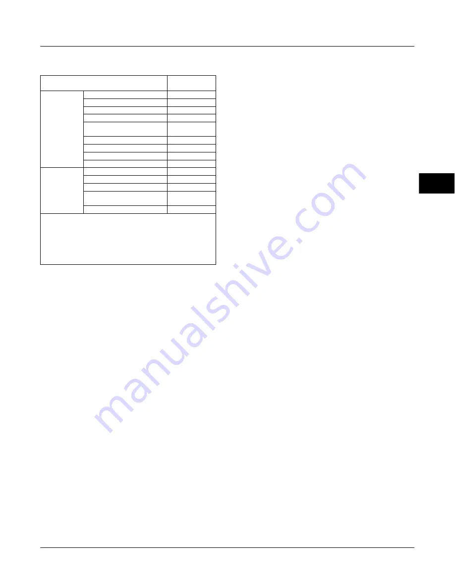
Table 4-1. Factory Default Detailed Setup Parameters
(continued)
Setup Parameter
Default
Setting
(1)
Informational
Status
Instrument Time Invalid Enable
No
Calibration in Progress Enable
No
Autocal in Progress Enable
No
Diagnostics in Progress Enable
No
Diagnostics Data Available
Enable
Yes
Integrator Saturated Hi Enable
Yes
Integrator Saturated Lo Enable
Yes
Pressure Control Active Enable
Yes
Multi-Drop Alert Enable
No
Alert Record
Valve Alerts Enable
Yes
Failure Alerts Enable
Yes
Miscellaneous Alerts Enable
No
Alert Record Has Entries
Enable
Yes
Alert Record Full Enable
No
1. The settings listed are for standard factory configuration. DVC6000 instruments
can also be ordered with custom configuration settings. For the default custom
settings, refer to the order requisition.
2. If the instrument is shipped mounted on an actuator, these values depend upon
the actuator on which the instrument is mounted.
3. In firmware 2 thru 6 this parameter is labeled Minimum Opening Time.
In firmware 10 and below this parameter should be set to zero (0).
4. In firmware 2 thru 6 this parameter is labeled Minimum Closing Time.
In firmware 10 and below this parameter should be set to zero (0).
5. Only available in firmware 7 and above. In firmware 7, 9, and 10 this parameter
should be set to zero (0).
Control Mode—You can change the control
mode by selecting Control Mode from the Mode and
Protection menu, or press the Hot Key and select
Control Mode.
Control Mode lets you define where the instrument
reads its set point. Follow the prompts on the Field
Communicator display to choose one of the following
control modes: Analog or Digital.
Choose Analog if the instrument is to receive its set
point over the 4-20 mA loop. Normally the instrument
control mode is Analog.
Choose Digital if the instrument is to receive its set
point digitally, via the HART communications link.
A third mode, Test, is also displayed. Normally the
instrument should not be in the Test mode. The Field
Communicator automatically switches to this mode
whenever it needs to stroke the valve during
calibration or stroke valve, for example. However, if
you abort from a procedure where the instrument is in
the Test mode, it may remain in this mode. To take
the instrument out of the Test mode, select Control
Mode then select either Analog or Digital.
Restart Control Mode—Lets you choose which
operating mode you want the instrument to be in after
a restart. Access by selecting Restart Control Mode
from the Mode and Protection menu. Follow the
prompts on the Field Communicator display to define
the restart control mode as Resume Last, Analog, or
Digital.
Burst Mode (1-2-1-4)
Enabling burst mode provides continuous
communication from the digital valve controller. Burst
mode applies only to the transmission of burst mode
data (analog input, travel target, pressure, and travel)
and does not affect the way other data is accessed.
Access to information in the instrument is normally
obtained through the poll/response of HART
communication. The Field Communicator or the
control system may request any of the information that
is normally available, even while the instrument is in
burst mode. Between each burst mode transmission
sent by the instrument, a short pause allows the Field
Communicator or control system to initiate a request.
The instrument receives the request, processes the
response message, and then continues “bursting” the
burst mode data.
To enable burst mode, select Burst Mode, and Burst
Enable from the Mode and Protection menu.
Burst Enable—Yes or no. Burst mode must be
enabled before you can change the burst mode
command.
Change Burst Enable—Turns Burst Mode on and
off. Actual values are Burst Enable = Disabled(Polled),
Enabled.
Burst Command—There are four burst mode
commands. Command 3 is recommended for use with
the 333 HART Tri-Loop HART-to-analog signal
converter. The other three are not used at this time.
Change Burst Command—Allows you to pick the
command to be sent from the instrument when Burst
Mode is on. Select HART Univ Cmd 1, HART Univ
Cmd 2, HART Univ Cmd 3, or DVC6000 Cmd 148.
Cmd 3 Configured Presssure—Command 3
provides the following variables:
Primary variable—analog input in % or ma,
Secondary variable—travel target in % of ranged
travel,
Tertiary variable—supply or output pressure in psig,
bar, kPa, or kg/cm
2
. Select Cmd 3 Configured
Pressure from the Burst menu to select if the output A,
output B, differential (A
−
B), or supply pressure is sent.
Quaternary variable—travel in % of ranged travel.
Protection
Protection—Some setup parameters may
require changing the protection with the Field
Communicator. To remove protection (change
protection to None) requires placing a jumper across
the Auxiliary terminals in the terminal box in order to
change protection.
4
Summary of Contents for Fisher FIELDVUE DVC6000
Page 2: ......
Page 22: ...DVC6000 Digital Valve Controllers September 2013 1 12 1 ...
Page 82: ...DVC6000 Digital Valve Controllers September 2013 4 22 4 ...
Page 94: ...DVC6000 Digital Valve Controllers September 2013 5 12 5 ...
Page 139: ...Loop Schematics Nameplates September 2013 B 1 B B Appendix B Loop Schematics Nameplates B ...
Page 161: ......


