


Chapter 5 Parameter Introductions 55
EV2000 Series Universal Variable Speed Drive User Manual
5.6 Close-loop Control Parameters(Group F5)
There are two kinds of close loop control: analog
close-loop control (feedback value is analog value) and
pulse close-loop control (feedback value is pulse). Fig.
5-29 and 5-30 show the typical wiring of analog
close-loop control and pulse close-loop control
respectively.
Water-
level
sensor
3-phase
380V
EV2000
U
V
W
PE
M
P24
CCI
VRF
VCI
GND
FWD
COM
1-3K
R
S
T
P
Output
.
G
N
D
.
.
.
.
.
.
.
QF
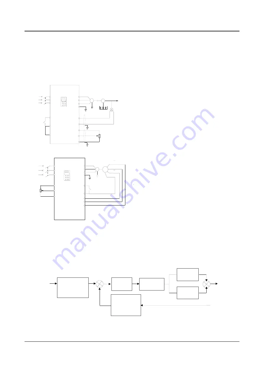
Fig. 5-29 Analog feedback control system with internal PI
VRF
VCI
GND
1-3K
R
S
T
3-phase
380V
QF
·
·
·
U
V
W
PE
M
FWD
COM
PG
A/A
B/B
PG supply
X7
P24
X8
PG GND
·
·
·
·
·
EV2000
Fig. 5-30 Wiring of speed close-loop with PG
Analog feedback control system:
An analog feedback control system uses a water-level
sensor as the feedback sensor of the internal PI.
As shown in Fig. 5-29, pressure reference (voltage
signal) is input via terminal VCI, while the feedback
pressure value is input into terminal CCI in the form of
0(4)~20mA current signal. The reference signal and
feedback signal are detected by the analog channel.
The start and stop of the drive can be controlled by
terminal FWD.
The above system can also use a TG (speed measuring
generator) in close speed-loop control
Close speed-loop using PG:
A close speed-loop control system uses external control
terminals X
7
and X
8
, and pulse generator(PG).
As shown in Fig. 5-30, reference of speed close-loop
can be input by a potentiometer in the form of voltage
signal via terminal VCI, while the feedback value of the
close loop is input by PG in pulse mode via terminals X7
and X8. The start and stop of the drive can be controlled
by terminal FWD.
In Fig. 5-30:
A and B are PG’s dual phase quadrature output;
P24 is connected to the power source of PG;
Speed reference is the voltage signal of 0~10V. The
voltage signal is in direct proportion to synchronous
speed n
0
that corresponds to 0~Max frequency (F0.05),
and
f
max
is Max frequency (F0.05), and P is the number
of poles of motor(FH.00).
n
0
=120
×
f
max
/P
Refer to F7.00~F7.07 for the functions of input terminals
X7 and X8.
Note:
1. The reference can also be input via panel or serial port;
2. Dual-phase input is good for improving the speed
measurement accuracy, while the wiring of single-phase
input circuit is simple;
3. Dual-phase pulse can only be input in quadrature mode;
4. If using the drive’s terminal P24 to supply the power to
PG, then the Max load current of optical PG must be less
than 100mA.
Operating principles of internal PI of EV2000 is shown in
the Fig. 5-301.
Reference
Reference
regulation
(F5.08 and F5.10)
ε
Error limit
(F5.15)
Output
+
-
Feedback
regulation
(F5.09 F5.11)
Feedback
KP×
(F5.12)
Ki ×
(F5.13)
Regulation
(F5.16)
ε
ε
∑
+
+
Fig. 5-31 PI block diagram


