


116 Appendix 3 Communication Protocol
EV2000 Series Universal Variable Speed Drive User Manual
5.4 Index Section
Meaning of Data: Auxiliary index bytes and command index bytes are included.
For the master, the auxiliary index and command index are used to cooperate with the master to accomplish concrete
functions.
For the slave, auxiliary index is used to report fault code. The command code will not be changed but reported directly.
Data type: Hex, four bytes. ASCII format.
Command code uses the lower two bytes, data range: “00”~”FF”.
Auxiliary code uses the higher two bytes, data range: “00”~”FF”.
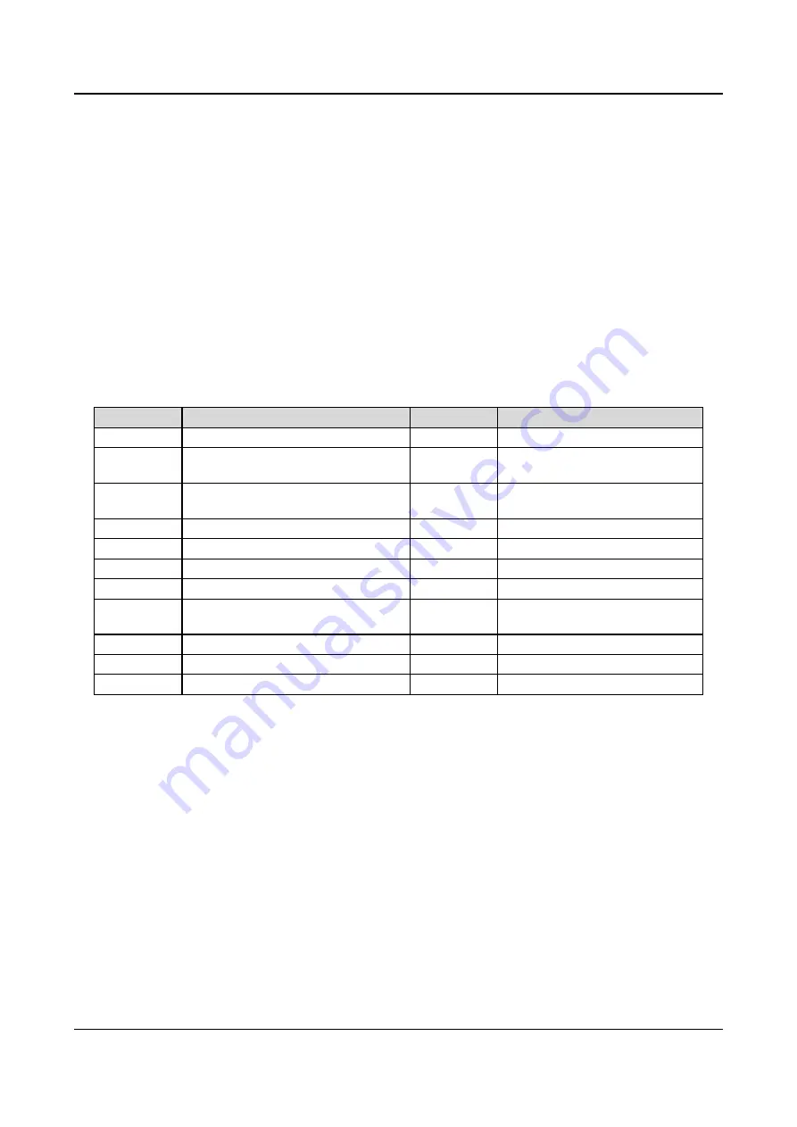
The fault code of the slave will occupy “auxiliary index” byte, see Table A-7.
Table A-7 Type of faults
Fault Index
Description of Fault
Fault Index
Description of Fault
01
Over current in Acc process
02
Over current in Dec process
03
Over current in constant-speed
Running process
04
Over voltage in Acc process
05
Over voltage in Dec process
06
Over voltage in constant-speed
Running process
07
Over voltage in stopping process
08
Phase failure of AC supply
09
Phase loss of drive’s AC output
10
IGBT fault
11
IGBT overheat
12
Rectifier bridge overheat
13
Drive overload
14
Motor overload
15
External equipment fault of emergent
stop
16 EEPROM
fault
17
Serial communication error
18
Contactor unclosed
19
Current detection error
20
CPU error
23
Parameters copy error
24
Auto-tuning error
5.5 Checksum
Meaning of Data: Frame verification. Four bytes. ASCII.
Calculation method: To sum up the ASCII values of all the bytes from “slave address” to “operation data”.
5.6 Frame Tail
Hex OD, Single byte.
1) Command list of protocols
In the following explanation, frame head 7E, frame tail OD, address and checksum are omitted. The format is ASCII
character.


