background image

9

8 Series

DESCRIPTION

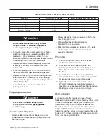
COEFFICIENT OF FRICTION

MULTIPLY TORQUE VALUE IN TABLE 5 BY

Machine Oil

f = 0.15

1.00

API SA2 Grease

f = 0.12

0.80

Never-Seez

®

 (Ni base)

f = 0.11

0.73

Never-Seez

®

 (Cu base)

f = 0.10

0.67

Molykote

®

 G-n Paste

f = 0.06

0.40

Table 6. 

Torque


Correction Factors for Common Lubricants

Molykote

®

 G-n is a mark owned by Dow Corning Corporation.

Never-Seez

®

 is a mark owned by Bostik, Inc.

CAUTION

Element assemblies are heavy and will 

require the use of adequate equipment 

and manpower to prevent injury.

3.  Thoroughly clean the gasket sealing faces being 

careful not to damage the sealing surface. For 

reassembly, lightly grease one side of a new 

gasket and place it in the machined recess of each 

interior flange on the two conical sections.

4. 

Replace the flame element assembly with a new 

assembly or properly cleaned and inspected 

existing unit.

5.  Loosen the jacking nuts on the tension rods until 

the flame cell assembly seats onto the gaskets.

6.  Replace all tensioning studs and hand tighten the 

outer nuts. Check to be sure that all the jacking 

nuts are completely loose and not making contact 

with the flange face.

7.  Torque the bolts in sequence as shown in 

Torquing Instruction.

Torquing Instruction

CAUTION

Excessive or uneven torquing can 

cause permanent damage to gaskets 

and housing.

Tools/Supplies Required

•  Hand operated conventional torque wrench or 

power assisted torque wrench appropriate for the 

specified torque.

• 

Socket wrenches of the proper size to fit the hex 

nuts being tightened

• 

Molydisulfide based lubricating paste, 

Molykote

®

 G-n or equivalent

•  Brush suitable for applying lubricant to the studs
•  Wiping rags necessary for the clean up of 

excessive lubricant

Procedure

1.  Use studs and nuts that are free of visible 

contamination and corrosion.

2.  Apply lubricant to the threads of the stud 

protruding outboard of the interior flanges and 

to the face of the hex nuts which will contact 

the flange.

3.  Assemble the nuts to the studs such that the 

amount of thread extending outboard beyond the 

nut is approximately equal on both ends.

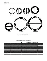
4.  Tighten the nuts to the torque values shown 

in Table 5 following the designated sequence, 

repeating the sequence as shown. Flange pattern 

tightening sequences are shown in Figure 4.

Bolt Lubrication

Lubrication will affect required torque of clean 

fasteners in good condition more than any other factor. 

In fact, 90% of applied torque goes to overcome 

friction while only 10% actually stretches the bolt. 

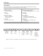
Table 5 assumes that only machine oil is used as a 

lubricant. Table 6 shows a list of several common 

lubricants and their effect on torque required to stretch 

bolts to 50% of their yield strength. Most are available 

from local bearing distributors.

Summary of Contents for ENARDO 8 Series

Page 1: ...dures performed by unqualified person may result in improper adjustment and unsafe operation Either condition may result in equipment damage or personal injury Only a qualified person shall install or service the 8 Series high pressure deflagration flame arrestor Introduction Scope of the Manual This manual provides specifications installation and maintenance instructions and parts ordering inform...

Page 2: ... mark owned by Haynes International Inc Specifications The Specifications table lists the specifications for the 8 Series high pressure deflagration flame arrestors Specification is stamped on the nameplate attached to the flame arrestor Available Construction See Table 1 and Figure 2 Gas Group B C and D Flange Size and Rating 2 to 24 in 50 to 600 mm CL150 FF and RF Housing Size 8 to 48 in 200 to ...

Page 3: ...signed to stop flames in the low medium and high pressure deflagration states Flame arrestor allows gas to pass though it but stops flame in order to prevent a larger fire of explosion Arrestor prevents flame by absorbing and dissipating the heat from flame as it attempts to travel through the spiral wound crimped ribbon flame cells These cells allow maximum flow with maximum protection See Figure...

Page 4: ...erify that the high pressure deflagration flame arrestor being installed has the appropriate gas group rating for your process This information is shown on the nameplate attached to the element housing Do not remove or alter this nameplate The measurement of the maximum gap between two equatorial flanges on a metal sphere that will prevent a flame from being transmitted from the sphere to the surr...

Page 5: ...e the auto ignition temperature of the process gas stream resulting in flame propagation through the arrestor See Table 3 for the endurance burn time of each gas group Pipe Lengths Extended lengths of pipe allow the flame to advance into more severe states of flame propagation such as high pressure deflagration or detonations High pressure deflagration flame arrestors should be installed in accord...

Page 6: ...Direction The Enardo high pressure deflagration flame arrestor is bi directional and can be installed either vertically or horizontally Consideration should be given to non symmetrical assemblies that include features such as clean out ports temperature monitoring device or other options that might have a preferred installation direction to suit the needs of the customer Piping Expansions and Redu...

Page 7: ... to maximize spray media penetration into the element Alternately spray each side of the element surface until clean 7 The cleaning interval should be governed by the amount and type of particulate in the system to which it is installed and must be determined by the user To determine the maintenance interval the user should check the element in the first few months of operation to find how quickly...

Page 8: ... 50 68 81608 2 1 8 Snug 25 34 50 68 75 102 82010 3 1 1 4 8 Snug 35 47 70 95 120 163 82412 4 1 1 4 8 Snug 35 47 70 95 120 163 82814 5 1 1 4 8 Snug 35 47 70 95 120 163 83016 6 1 1 4 8 Snug 35 47 70 95 120 163 83620 7 1 1 2 8 Snug 50 68 120 163 170 230 1 Using machine oil as lubricant See Bolt Lubrication section on page 9 and torque correction factors for other lubricants in Table 6 2 See Figure 4 P...

Page 9: ...e permanent damage to gaskets and housing Tools Supplies Required Hand operated conventional torque wrench or power assisted torque wrench appropriate for the specified torque Socket wrenches of the proper size to fit the hex nuts being tightened Molydisulfide based lubricating paste Molykote G n or equivalent Brush suitable for applying lubricant to the studs Wiping rags necessary for the clean u...

Page 10: ...mum downtime it is recommended that the user purchase a spare element assembly and several spare element gaskets The spare element assembly can be installed immediately and the dirty assembly can then be cleaned and be stored as a spare for the next maintenance interval Note Element gaskets should be replaced each time the cell assembly is loosened and removed to insure a gas tight seal Parts Orde...

Page 11: ...nless Steel Model Part Number 80802 80803 80804 8000903 8000922 8000901 81206 8000904 8000923 8000905 81608 8000906 8000924 8000907 82010 8000908 8000925 8000909 82412 8000910 8000926 8000911 82814 8000912 8000927 8000913 83016 8000914 8000928 8000915 83620 8000918 8000930 8000919 Table 8 Replacement Element Assemblies Part Numbers Group D Gas ...

Page 12: ... guarantees express or implied regarding the products or services described herein or their use or applicability We reserve the right to modify or improve the designs or specifications of such products at any time without notice Emerson Process Management Regulator Technologies Tulsa LLC does not assume responsibility for the selection use or maintenance of any product Responsibility for proper se...

Reviews: