background image

8 Series

6

Standard compressed fiber gaskets that will 

withstand temperatures of 450°F / 232°C or higher 

are normally used, but other materials of equal or 

higher temperature capability may be used at the 

customer’s discretion.

Positioning

CAUTION

The high pressure deflagration 

flame arrestor is fitted with lugs for 

lifting the element assembly during 

servicing operations. These lugs are 

not intended for lifting the entire unit 

during installation. Damage to the high 

pressure deflagration flame arrestor may 

result from improper lifting. The units 

should be lifted using appropriately 

rated Nylon (PA) straps rigged on the 

outside of the tension studs.

The arrestor should be positioned such that the 

element is accessible for removal. The tension studs 

are supplied with jacking nuts on one half of the bolting 

circumference. Install the unit so that the jacking nuts 

(on the inside of the studs) are positioned on the 

opposite side from the direction that the element 

assembly will be removed.
Models that have drain plugs are designed for 

horizontal installation and should be installed with the 

drain plugs aligned at the bottom of the unit. Models 

that have pressure taps are designed to allow pressure 

gauges to be installed on both sides of the flame cell 

assembly to determine blockage. The pressure taps 

should be aligned at the top to allow easy viewing 

of the gauges. Units that are equipped with optional 

internal cleaning systems should be connected to a 

source of cleaning media such as water, steam or 

other suitable solvent.
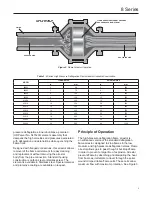
Flow Direction

The Enardo high pressure deflagration flame arrestor 

is bi-directional and can be installed either vertically or 

horizontally. Consideration should be given to non-

symmetrical assemblies that include features such 

as clean-out ports, temperature monitoring device or 

other options that might have a preferred installation 

direction to suit the needs of the customer. 

Piping Expansions and Reductions 

Adjacent to High Pressure Deflagration 

Flame Arrestors

WARNING

!

No instrument, tubing or other device 

whatsoever shall circumvent the high 

pressure deflagration flame arrestor 

in such a manner to allow a flame path 

to exist around the flame element of 

the arrestor. When instrumentation is 

installed in such a manner that it creates 

a path circumventing the flame element 

of an arrestor, measures must be taken 

to prevent passage of flame through the 

instrumentation device and/or system. 

Instrumentation must be capable 

of withstanding the maximum and 

minimum pressures and temperatures to 

which the device may be exposed and at 

a minimum be capable of withstanding 

a hydrostatic pressure test of 350 psig / 

24 bar.

An Enardo high pressure deflagration flame arrestor 

may be installed in any vapor control line that is 

smaller than or equal to the nominal pipe diameter of 

the arrestor’s connection flanges. 

When it is necessary to increase the diameter of the 

piping on the downstream side of the high pressure 

deflagration flame arrestor, a length of pipe at least 

120 pipe diameters must be installed between the 

high pressure deflagration flame arrestor and the 

expansion. A pipe diameter is considered as the 

inside diameter of pipe having a nominal size equal 

to the high pressure deflagration flame arrestor’s 

connecting flanges.

Summary of Contents for ENARDO 8 Series

Page 1: ...dures performed by unqualified person may result in improper adjustment and unsafe operation Either condition may result in equipment damage or personal injury Only a qualified person shall install or service the 8 Series high pressure deflagration flame arrestor Introduction Scope of the Manual This manual provides specifications installation and maintenance instructions and parts ordering inform...

Page 2: ... mark owned by Haynes International Inc Specifications The Specifications table lists the specifications for the 8 Series high pressure deflagration flame arrestors Specification is stamped on the nameplate attached to the flame arrestor Available Construction See Table 1 and Figure 2 Gas Group B C and D Flange Size and Rating 2 to 24 in 50 to 600 mm CL150 FF and RF Housing Size 8 to 48 in 200 to ...

Page 3: ...signed to stop flames in the low medium and high pressure deflagration states Flame arrestor allows gas to pass though it but stops flame in order to prevent a larger fire of explosion Arrestor prevents flame by absorbing and dissipating the heat from flame as it attempts to travel through the spiral wound crimped ribbon flame cells These cells allow maximum flow with maximum protection See Figure...

Page 4: ...erify that the high pressure deflagration flame arrestor being installed has the appropriate gas group rating for your process This information is shown on the nameplate attached to the element housing Do not remove or alter this nameplate The measurement of the maximum gap between two equatorial flanges on a metal sphere that will prevent a flame from being transmitted from the sphere to the surr...

Page 5: ...e the auto ignition temperature of the process gas stream resulting in flame propagation through the arrestor See Table 3 for the endurance burn time of each gas group Pipe Lengths Extended lengths of pipe allow the flame to advance into more severe states of flame propagation such as high pressure deflagration or detonations High pressure deflagration flame arrestors should be installed in accord...

Page 6: ...Direction The Enardo high pressure deflagration flame arrestor is bi directional and can be installed either vertically or horizontally Consideration should be given to non symmetrical assemblies that include features such as clean out ports temperature monitoring device or other options that might have a preferred installation direction to suit the needs of the customer Piping Expansions and Redu...

Page 7: ... to maximize spray media penetration into the element Alternately spray each side of the element surface until clean 7 The cleaning interval should be governed by the amount and type of particulate in the system to which it is installed and must be determined by the user To determine the maintenance interval the user should check the element in the first few months of operation to find how quickly...

Page 8: ... 50 68 81608 2 1 8 Snug 25 34 50 68 75 102 82010 3 1 1 4 8 Snug 35 47 70 95 120 163 82412 4 1 1 4 8 Snug 35 47 70 95 120 163 82814 5 1 1 4 8 Snug 35 47 70 95 120 163 83016 6 1 1 4 8 Snug 35 47 70 95 120 163 83620 7 1 1 2 8 Snug 50 68 120 163 170 230 1 Using machine oil as lubricant See Bolt Lubrication section on page 9 and torque correction factors for other lubricants in Table 6 2 See Figure 4 P...

Page 9: ...e permanent damage to gaskets and housing Tools Supplies Required Hand operated conventional torque wrench or power assisted torque wrench appropriate for the specified torque Socket wrenches of the proper size to fit the hex nuts being tightened Molydisulfide based lubricating paste Molykote G n or equivalent Brush suitable for applying lubricant to the studs Wiping rags necessary for the clean u...

Page 10: ...mum downtime it is recommended that the user purchase a spare element assembly and several spare element gaskets The spare element assembly can be installed immediately and the dirty assembly can then be cleaned and be stored as a spare for the next maintenance interval Note Element gaskets should be replaced each time the cell assembly is loosened and removed to insure a gas tight seal Parts Orde...

Page 11: ...nless Steel Model Part Number 80802 80803 80804 8000903 8000922 8000901 81206 8000904 8000923 8000905 81608 8000906 8000924 8000907 82010 8000908 8000925 8000909 82412 8000910 8000926 8000911 82814 8000912 8000927 8000913 83016 8000914 8000928 8000915 83620 8000918 8000930 8000919 Table 8 Replacement Element Assemblies Part Numbers Group D Gas ...

Page 12: ... guarantees express or implied regarding the products or services described herein or their use or applicability We reserve the right to modify or improve the designs or specifications of such products at any time without notice Emerson Process Management Regulator Technologies Tulsa LLC does not assume responsibility for the selection use or maintenance of any product Responsibility for proper se...

Reviews: