


1592028000 XWEB300D_500_500D opr GB r2.2.0 2013.08.01.docx XWEB500/300 85/114
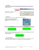
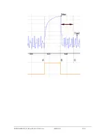
check interval can be used as a check if the controllers really defrost. If there is no defrost for a period of
longer than this parameter, the C.R.O. will add a warning to the graph report.
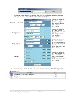
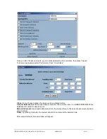
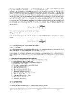
Reference class is the group of controllers involved in the data analysis of the worst case. Controller is the
device made by Dixell that controls the compressor rack. Set point let the user choose the right set-point
(usually the suction set-point). The parameter for the worst case calculation (represented in percentage), let
the user define a threshold for the C.R.O.: below the value there is no action, above the algorithm sends the
new set-point. Dead band is set across the worst case set parameter and defines a neutral band: here inside
no action is starter. The algorithm to modify the suction pressure needs to know the initial value of this figure.
The Initial pressure parameter is used to set this value. Min./Max. suct. Press. Parameters are security limits
for the C.R.O. We strongly suggest to add this entries to prevent the algorithm to set set-point values out of
bound. Release and Call gain parameters control the new set-point value according to the following
formulas. If the real-time percentage is below the one setup in worst case set (dead band is computed), the
new set-point is:
1000
%
gain
old
new
RLS
Set
Set
%
(real-time percentage) – (worst case set percentage)
gain
RLS
release gain
If the real-time percentage is above the one setup in worst case set (dead band is computed), the new set-
point is:
1000
%
gain
old
new
CALL
Set
Set
%
(real-time percentage) – (worst case set percentage)
gain
CALL
call gain
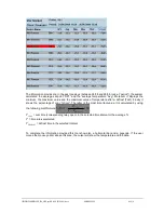
The real-time percentage is the worst percentage present in the installation according to the quantity of cool
power requested by all the controllers during the back analysis interval.
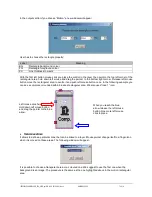
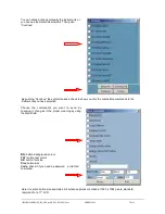
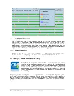
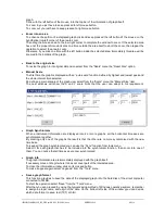
Finally it is possible to simulate the set-point modifications: select acquire data only. To activate the C.R.O.
press enable engine. To deactivate the C.R.O. press disable engine. To view the graph report, go to view
menu.
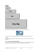
E
RRORS HANDLED ON PARAMETERS WINDOW
In case the system returns an error on confirming parameters, please check:
a) A device/setpoint needs to be selected
b) Device/Setpoint is not used by another active CRO motos
c) A class needs to be selected
d) The class is already used by another CRO motor
e) ‘Worst Case Set’ shall be >= 0
f) ‘Dead band’ shall be >= 0
g) ‘Execution interval’ shall be > 0
h) ‘Back analysis interval’ shall be > 0
i)
‘Defrost check interval’ shall be >=0
j)
‘Cycle time’ shall be > 0 if cycling is enabled
k) ‘MAX’ shall be >= ‘MIN’
l)
‘Initial Set Value’ shall be <= ‘MAX’
m) ‘Release gain’ shall not be 0
n) ‘Call Gain’ shall not be 0
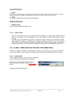
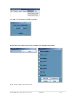
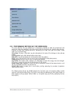
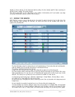
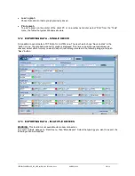
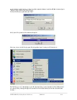
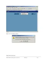
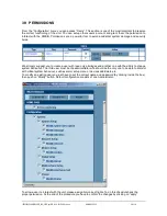
3.7 DATA MENU
You can access data information from the roll-down menu “Data” -> “Graphs”.
Summary of Contents for Dixell XWEB300
Page 1: ...OPERATION MANUAL v 2 2 0 ...
Page 2: ...1592028000 XWEB300D_500_500D opr GB r2 2 0 2013 08 01 docx XWEB500 300 2 114 ...
Page 80: ...1592028000 XWEB300D_500_500D opr GB r2 2 0 2013 08 01 docx XWEB500 300 80 114 ...
Page 96: ...1592028000 XWEB300D_500_500D opr GB r2 2 0 2013 08 01 docx XWEB500 300 96 114 ...


