


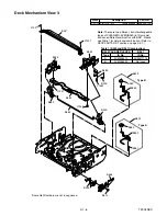
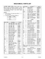


2-4-7
U25NDA
[24]
(C-5)
(S-12)
[25]
[27]
[26]
[28]
(C-4)
(L-4)
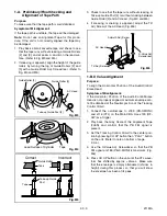
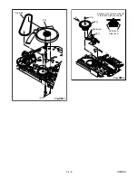
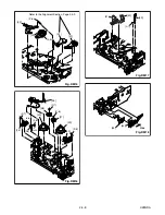
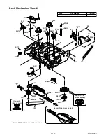
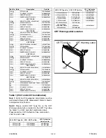
When reassembling [28],
meet the first groove on
[28] to the first tooth on
[44] as shown.
[28]
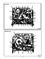
Top View
First tooth on [44]
First groove on [28]
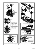
Align [25] and [28] as shown.
Bottom View
[28]
[25]
Pin of [33]
Pin of [30]
Position of Mode Lever when installed
Pin of [34]
Fig. DM14
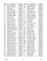
[23]
(P-4)
(C-3)
(P-4)
[28]
[28]
[23]
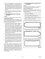
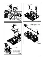
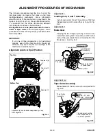
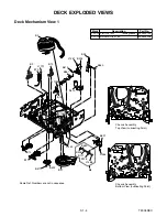
When installing [23], install
the spring (P-4) to [28] as
shown in the left figure, and
then install [23] while
pressing the spring (P-4) to
the direction of the arrow in
the left figure and confirming
that the position of the
spring (P-4) is placed as
shown in the left figure.
Pin on
bottom
of [23]
Pin on [22]
Position of p
in on [22]
Top View
(C-2)
[22]
Fig. DM13
Summary of Contents for 6319CC
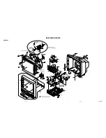
Page 18: ...1 6 2 T7300DC Fig 1 ANT S 1 S 1 1 REAR CABINET S 1 S 1 S 1 S 1 Fig 2 ...
Page 20: ...1 6 4 T7300DC Fig 4 S 5 S 5 S 5 S 5 5 CRT CRT CBA ANODE CAP ...
Page 75: ...Packing X 1 S 1 S 4 S 3 S 3 S 2 TAPE TAPE X 4 X 3 X 2 X 7 S 6 S 14 FRONT 3 1 3 T7300PEX ...
Page 92: ...Printed in Japan 2002 02 20 HO SC319C 6319CC EWC1902 T7300UA 2UC 3UD ...


